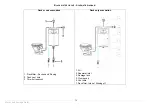
82
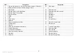
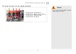
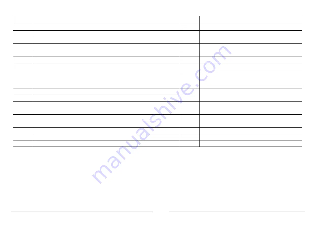
REF
Designation
REF
Designation
1
General electrical panel + Control of the battery b Differ
20
Water maker
2
Battery isolation switch set + Battery c Fuses
3
Bow thruster
22
Microwave oven
4
Electrical panel - Inside wheelhouse
23
Microwave oven flush mounted
5
Electrical panel - Flying bridge
24
Hot plate
6
Electric windlass
25
Dishwasher
7
Fridge
26
Ice maker
8
Hifi
27
Washer
9
Water heater
28
Air conditioning
10
Batteries
11
Engine compartment ventilator
30
Video Hifi - forward cabin
12
Aft bilge pump
31
Electric toilet
13
Demister
14
Water unit + Windlass circuit breaker
33
Cool box Flying bridge
15
Forward bilge pump
34
Deck searchlight
16
Shore power socket 220V
35
Stern thruster
17
Shore power socket Generator
36
Hydraulic gangway
18
Generator
37
Electronic interior
19
Auto pilot
38
Electronic Flying bridge
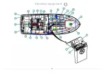
Electrical equipment
Summary of Contents for SWIFT TRAWLER 42
Page 1: ...SWIFT TRAWLER 42 Code 087851 Index C Owner s Manual ...
Page 2: ......
Page 4: ......
Page 7: ...3 Introduction HISTORY OF UPDATES Index A 10 2008 Index B 01 2010 Index C 09 2010 ...
Page 8: ......
Page 10: ......
Page 11: ...7 General specifications Technical specifications Certification Design category Your boat 1 ...
Page 16: ......
Page 26: ......
Page 30: ...26 USE OF THE MANUAL BILGE PUMP Location Operation Capacity 40 5 litre minute Safety ...
Page 34: ......
Page 35: ...31 Hull Maintenance of the Hull Lifting 3 ...
Page 36: ...32 LIFTING Wetted area 48 m Hull ...
Page 38: ......
Page 46: ......
Page 48: ......
Page 49: ...45 Steering system Steering Gear 5 ...
Page 52: ...48 ACCESS TO ELEMENTS ENGINE COMPARTMENT Steering pump Steering components Steering system ...
Page 53: ...49 Interior Introduction Interior maintenance Maintenance of fabrics 6 ...
Page 54: ...50 INTRODUCTION Interior ...
Page 58: ......
Page 63: ......
Page 67: ......
Page 69: ......
Page 75: ......
Page 79: ...75 Water and sewage water 7 ...
Page 80: ......
Page 82: ......
Page 84: ...80 MAIN ELEMENTS SCHEMATIC DIAGRAM ELECTRICAL CIRCUIT 12 V Electrical equipment ...
Page 85: ...81 Electrical equipment 8 ...
Page 89: ......
Page 91: ......
Page 98: ...94 LEAD LINES Transducer location View interior View Outside Electrical equipment ...
Page 106: ......
Page 107: ...103 Engine General information Engine installation 9 ...
Page 108: ......
Page 110: ...106 Fuel filler Starboard gangway position Tank interconnecting valve Engine ...
Page 112: ...108 1 1 2 3 4 5 6 7 8 9 10 Engine ...
Page 114: ......
Page 116: ......
Page 122: ......
Page 124: ......
Page 125: ...121 Launching Launching recommendations 10 10 ...
Page 126: ...122 POSITION OF HOISTING CRADLE AND STRAPS Note Measurements are expressed in mm Launching ...
Page 128: ......
Page 129: ...125 Winter Storage Laying up Protection and maintenance 11 11 ...
Page 130: ......

