background image

Albatros


DII


36”


Page


1


Copyright©


2005

11


M.K.


Bengtson


All


Rights


Reserved


Rev


07/11


Albatros


DII


Thank


you


for


purchasing


the


Albatros


DII


model


for


electric


flight.


THE


MODEL


A


semi


scale


adaptation


of


the


Albatros


DII,


this


model


is


designed


to


be


easy


to


build


and


exciting


to


fly

.


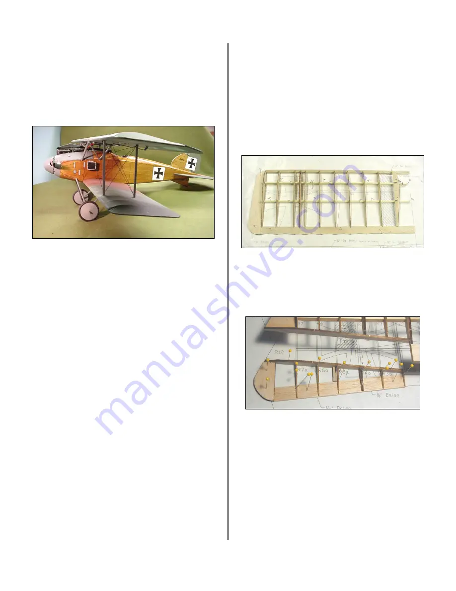
Finished


Model


by


Dave


Ottney


POWER


SET


UP


The


6V


S400


motor


powers


the


model


using


the


Mini

Olympus


2.33:1


Gearbox


and


a


10x4.7


APC


prop.


Battery


power


pack


is


an


8


cell


600maH


Nicad


or


an


equivalent


weight


Nimh


SPECIFICATIONS


More


than


215


laser


cut


parts


Scale:


~1/10


Wingspan:


36

ʺ  

Wing


Area:


442


sq


in


Weight:


24


oz


Channels:


R/E/A/T


Power


System:


Speed


400,


Mini

Olympus


2.33:1


gearbox


Prop:


10x6


Wheels:


Balsa


&


plywood,


Neoprene


foam


tires


Airfoil


Type:


Flat


bottomed


Spinner:


F

oam


and


fiberglass


Decals:


Available


on


website


Covering:


Litespan


or


Polyspan


BUILDING


THE


MODEL


BEFORE


STARTING


A


note


about


the


photos:


The


photos


were


taken


of


a


prototype


and


the


parts


supplied


may


look


slightly


different


from


them.


However,


the


concepts


illustrated


are


the


same.


WINGS


Wing


Construction


Pin


down,


over


the


plan,


the


t/e,


spars


and


wing


tip,


gluing


as


required.


Add


the


leading


edge


stock


after


the


basic


frame


is


done


as


the


stock


is


inserted


in


a


rotated


fashion.


Add


the


wing


tips


and


align


the


front


tip


along


the


center


of


the


leading


edge.


Sand


the


leading


edge


stock


to


be


rounded


and


meet


the


ribs.


Wing


Pinned


to


Plan


Scalloping


can


be


done


easily


by


fitting


sandpaper


on


a


dowel


or


other


appropriately


shaped


object


and


simply


sand


the


scallops.


Start


sanding


at


the


center


point


of


the


scallop


and


stop


as


soon


as


the


desired


depth


is


reached.


Wing


Detail


(Note:


Photo


is


of


the


Albatros


DIII


Aileron)


The


leading


edge


of


the


aileron


is


rounded


over


with


sandpaper


to


make


the


aileron


movable


with


a


minimum


gap.


The


trailing


edge


of


the


wing


in


that


section


is


left


flat.


FUSELAGE


CONSTRUCTION


The


fuselage


is


built


as


two


side


structures,


which


are


then


joined


over


the


plan.


This


system


not


only


keeps


each


stage


simple,


but


it


also


helps


to


ensure


a


straight


fuselage.


Summary of Contents for Albatros DII

Page 1: ...n All Rights Reserved Rev 07 11 Albatros DII R C Scale Model Instructions CONTACT INFORMATION The Albatros DII was designed by M K Bengtson Manufactured and Distributed by Bengtson Company e mail sales aerodromerc com Web Site www aerodromerc com ...

Page 2: ...rototype and the parts supplied may look slightly different from them However the concepts illustrated are the same WINGS Wing Construction Pin down over the plan the t e spars and wing tip gluing as required Add the leading edge stock after the basic frame is done as the stock is inserted in a rotated fashion Add the wing tips and align the front tip along the center of the leading edge Sand the ...

Page 3: ...t Place F7 carefully It is designed to run down the centerline of the fuselage It serves to position the vertical stabilizer and tail skid Use a length of 1 4 diameter birch or hard balsa dowel at the end of the fuselage This gives the fuselage a nice rounded termination Fuselage Construction Detail Fuselage Bottom Stringers Fuselage Nose Filler Balsa Blocks Sand Fuse to Shape Adding the Decking A...

Page 4: ...weighs only 3 oz Adding The Undercarriage Plates Remove from the board and add the plywood crosspieces that serve as u c plates TAIL SURFACES Lay out and glue parts of the tail surfaces on the plans Tail Surface Detail Sand the tail parts rounding off all edges Don t add the horns or hinge the surfaces until after covering is complete Tail Surfaces Pinned on Plans LANDING GEAR The undercarriage is...

Page 5: ... other materials Solid 16 gauge copper electrical wire black insulated makes an excellent radiator hose Spinner Components The spinner is composed of fiberglassed blue foam The spinner is made from blue foam which is tack glued to a piece of 1 32 ply Epoxy a short 1 4 diameter dowel to the back in the center of the disk Place the assembly in a drill chuck and sand the foam to shape while it spins ...

Page 6: ...very nice scale appearance INSTALLING THE RADIO CONTROL GEAR Aileron Servos Aileron servos are mounted in wing and attached with short threaded rods to the ailerons Use a Y wiring harness connector to wire the servos to a single radio connection If differential aileron throws are desired rotate each servo horn forward about 20 degrees while maintaining the neutral position of the aileron This shou...

Page 7: ...he model may require hand launching Be careful that your hand or fingers do not catch on the lower rigging Launch firmly and level Let the model gain altitude slowly off the runway Applying too much up elevator at slow speeds risks a stall Make your turns gently as tight turns risk tip stalling in any model Don t expect the elevator to make the model climb Think of the elevator as a device to chan...

Reviews: