background image


Introduction 

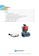
This manual explains the working of the Benisol with the automated three way valve. The components 
are made in Belgium by Beniferro BV and are of the highest quality. The control- unit measures pool 
and EPDM temperature with 2 sensors and activates accordingly the three- way-valve. 
 
The 3 way valve has gear wheels made of steel and are virtually unbreakable. If you in the rare occasion 
do experience trouble, please read our troubleshooting manual or contact your dealer. 


Attention! 

 
Damage  caused  by  not  following  these  introductions  is  not  covered  by  warranty. 
 
The J2-H series is suitable for voltages between 85-240V. With normal use 

it’s

 not needed to 

remove the cap of the automatic 3-way valve. During proceedings you need to make sure the 
voltage is turned off. It is recommended to let the electrical installation be adjusted by a 
qualified technician.                                             
 
The automatic 3-way valve is controlled by micro switch. If the power supply is interrupted 
when the valve was opening or closing, the valve will stop. As soon as the valve receives 
power again, the valve will continue in the same position. 


Summary of Contents for BENISOL

Page 1: ...Automated Three Way Valve BENISOL...

Page 2: ...4 2 Temperature sensors of the Harmosol 5 3 Setting the delta temperature and maximum water temperature 6 4 Connecting the automatic valve with the Harmosol 7 5 Connecting the Benisol to a filter pum...

Page 3: ...g manual or contact your dealer Attention Damage caused by not following these introductions is not covered by warranty The J2 H series is suitable for voltages between 85 240V With normal use it s no...

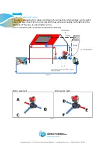
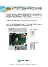
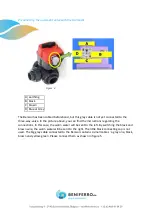
Page 4: ...the connection scheme below As the water enters the valve from the front it is possible to have the solar heating to the left or to the right side of the valve by adjusting the wiring see 4 Connecting...

Page 5: ...teflon insert in the filter outlet When first installing the Benisol the probes will not be attached and should be attached by yourself Please connect the probes as in figure 3 The right temperature...

Page 6: ...low circle Usually a difference of 4 degrees is chosen In the example photograph below when the outer air is more than 4 C warmer than the water the automatic valve or pump will be activated and the w...

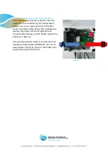
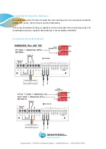
Page 7: ...e In the picture above you can find the instructions regarding the connections In this case the warm water will be sent to the left By switching the black and brown wire the warm water will be sent to...

Page 8: ...r heating system via a separate circulation system with pump rather than via an automated valve In this case the black and the grey cables are to be connected to the circulation pump The remaining bro...

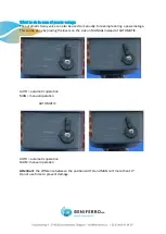
Page 9: ...poweroutage This can be done by placing the levers on the side on MANUAL instead of AUTOMATIC AUTO automatic operation MAN manual operation AUTOMATIC AUTO automatic operation MAN manual operation Att...

Reviews: