
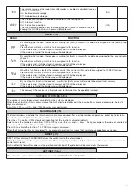
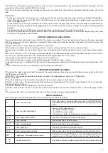

16
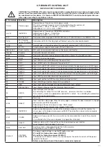
Fuse
Type
Description
F1
250V T1A
Protection, power supply of accessories
F2
250V T400mA
Protection, logics of board
F3
250V T630mA
Protection, common inputs and serial of inverter
F4
500V T125mA
Protection, transformer primary
F5
250V T500mA
Protection, lashing light, 230V
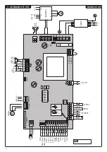
HOW TO CHECK CONNECTIONS
1) Cut off power supply.
2) Manually release the door/gate and push it for about half stoke. Lock the door again.
3) Restore power supply.
4) Send a step-by-step command through push-button <->* on the control unit (LCD display off). To stop the door/gate press <->* once
more.
5) The door/gate should open. If not, use the MINV logics to change the opening direction.
* Bison 25: <+>
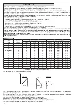
INVERTER
The CP.BISON OTI control unit is provided with serial connections for the control of a pre-installed inverter on the gear motors of the
BISON series.
The inverter allows to enhance the functional performance of the motor as regards control of the torque, speed and safety.
Although the pre-installed inverter is provided with programming functions, none of them must be changed by the installer because the
CP.BISON control unit directly controls all the operating parameters. If the device is to be replaced, ask an original spare part to the
manufacturer and carry out its wiring in compliance with connections shown in the handbook supplied with the spare part itself. Do not
use inverters which are not supplied by the manufacturer for any reason whatsoever.
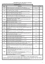
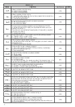
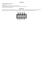
PROGRAMMING
The programming of the various functions of the control unit is carried out using the LCD display on the control unit and setting the
desired values in the programming menus described below.
The parameters menu allows you to assign a numerical value to a function, in the same way as a regulating trimmer.
The logic menu allows you to activate or deactivate a function, in the same way as setting a dip-switch.
Other special functions follow the parameters and logic menus and may vary depending on the type of control unit or the software
release.
TO ACCESS PROGRAMMING
1 – Press the button <OK>, the display goes to the first menu, Parameters “PAR”.
2 – With the <+> or <-> button, select the menu you want.
3 – Press the button <OK>, the display shows the first function available on the menu.
4 – With the <+> or <-> button, select the function you want.
5 – Press the button <OK>, the display shows the value currently set for the function selected.
6 – With the <+> or <-> button, select the value you intend to assign to the function.
7 – Press the button <OK>, the display shows the signal “PRG” which indicates that programming has been completed.
NOTES
Pressing <-> with the display turned off means an impulse of P.P.
Simultaneously pressing <+> and <-> from inside a function menu allows you to return to the previous menu without making any
changes.
Hold down the <+> key or the <-> key to accelerate the increase/decrease of the values.
After waiting 30s the control unit quits programming mode and switches off the display.


