background image

6

7

Control units CP.K3-RE / CP.K3-RI / CP.K4-RE / CP.K4-RI

Control units for 24Vdc motors with powers under 120W.

GENERAL RULES 

a)  The electrical installation and operating logic must comply with statutory regulations.
b)  Cables  of  different  voltages  must  be  physically  separated  or  otherwise  adequately  screened  with 

secondary insulation of at least 1 mm.

c)  Cables must be secured by additional clamps next to their terminals.
d)  Control all wiring connections are correct before powering.
e)  Check the Dip-Switch settings are correct.
f)  Unused N.C. inputs must be jumpered.

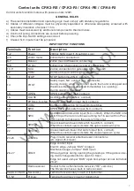
INPUT/OUTPUT FUNCTIONS

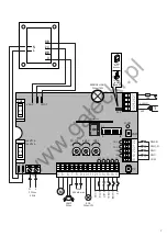
Terminals

Function

Description

1-2

Power

230Vac 50Hz input (1-Neutral/2-Live)

4-5

24Vdc motor

24Vdc motor connection

6-7

Beacon

24Vac max 40W beacon connection 

8-9

24 Vac

24Vac/max 0.5A accessory power connection 

10-11

SCA

24 Vac connection for gate open light – max 3W 

12

COM

Common for all control signal inputs. 

13

STOP

STOP button input (N.C. contact) 

14

PHOT

Safety input, N.C. contact (e.g. photocells)
During closing: when the contact opens the motor is stopped and 
the stroke direction is reversed immediately (i.e. opening).
During opening: disabled.

15

OPEN

OPEN button input (N.O. contact)

16

CLOSE

CLOSE button input (N.O. contact)

17

PP Step-by-step Step-by-step button input (N.O. contact) 

18

COM

Common connection for travel limit switches. 

19

SWO

OPEN travel limit switch input (N.C. contact).

20

SWC

CLOSE travel limit switch input (N.C. contact). When the SWC limit 
switch trips the motor continues running for 1.5 sec (with no Prox-
imity signal) to make sure the gate is firmly shut.

21

SWO-R

Open slowdown travel limit switch input (N.C. contact). 
When this contact opens it starts the open slowdown cycle.

22

SWC-R

Close slowdown travel limit switch input (N.C. contact). 
When this contact opens it starts the close slowdown cycle.

24-25

Antenna

Plug-in radio receiver antenna board connections
(24-signal/25-screen). 

26-27

EDGE

Edge contact input 
Electric edge: Jumper “DAS” bridged
Mechanical edge: Jumper “DAS” open
If the edge trips during opening the gate stops. If the gate is clos-
ing it will change direction to open for 3 sec.
Edge not used: Jumper “DAS” open and jumper across terminals 
26-27.

J2

Radio receiver

Socket for two channel radio receiver (“RE” versions)
The RI versions have a built-in radio receiver

VAUX-0-VMOT Secondary

Terminal for secondary circuit of transformer

L1-N1

Primary

Terminal for primary circuit of transformer

www.ga

ł

ecki.pl

Summary of Contents for CP.K3-RE

Page 1: ...EROWANIA L8542371 Rev 07 05 00 CP K3 RE CP K3 RI CP K4 RE CP K4 RI Libro istruzioni Operating instructions Betriebsanleitung Livret d instructions Manual de instrucciones Ksi eczka z instrukcjami UNIO...

Page 2: ...omagn tique Reglamento de compatibilidad electromagn tica 89 336 MCE 93 68 MCE Wytyczna odno nie zdolno ci wsp dzia ania elektromagne tycznego 89 336 EWG 93 68 EWG Norme armonizzate applicate in parti...

Page 3: ...4Vac 500mA max 11 10 9 8 7 6 5 13 12 14 15 16 17 4 21 22 20 19 18 25 26 27 24 TCA AMP O AMP C F2 230V T1A 120V T2A F1 2AF 1 8 30 24 N L 0 20 SCA 24Vac 3W LAMP 24Vac POWER STP PH OP CH PP SWO SWC P P P...

Page 4: ...a contatto N C ad es fotocellule In fase di chiusura l apertura del contatto provoca l arresto del mo tore e l inversione istantanea della direzione di marcia dello stesso apre In fase di apertura non...

Page 5: ...RE CHIUDE la pressione su questi pulsanti deve essere mantenuta per tutta la durata della manovra movimento controllato a vista Ingressi PHOT e P P e COSTA disabilitati Sensore amperometrico e STOP at...

Page 6: ...ertura SWO R Led SWC R Si spegne con l attivazione del finecorsa di rallentamento chiusura SWC R La centrale inoltre prima di ogni manovra esegue un controllo di corretto funzionamento Se questo contr...

Page 7: ...g opening disabled 15 OPEN OPEN button input N O contact 16 CLOSE CLOSE button input N O contact 17 PP Step by step Step by step button input N O contact 18 COM Common connection for travel limit swit...

Page 8: ...n and the transmitter Off operating sequence OPEN STOP CLOSE STOP On operating sequence OPEN CLOSE OPEN DIP 5 Fast AMP Enables or disables the rapid amperometric function Off in the close cycle the am...

Page 9: ...nd the Power LED blinks rapidly to signal there is a fault Configuration with built in receiver only RI versions The control unit is fitted with a built in radio module for receiving remote controls b...

Page 10: ...ffnen des Kontakts wird der Motor ange halten und seine Gangrichtung umgehend umgekehrt Schlie en W hrend des ffnens nicht aktiv 15 OPEN Eingang Taste FFNEN Arbeitskontakt 16 CLOSE Eingang Taste SCHL...

Page 11: ...EN SCHLIESSEN sind aktiv Die Tasten m ssen w hrend des gesamten Man vers gedr ckt gehalten werden Bewegung mit Sichtkontrolle Eing nge PHOT und P P Schrittschaltung und KONTAKTLEISTE deaktiviert Amper...

Page 12: ...bei Ausl sen des Endschalters f r Verlangsamung des ffnens SWO R aus LED SWC R Schaltet sich bei Ausl sen des Endschalters f r Verlangsamung des Schlie ens SWC R aus Au erdem f hrt die Zentrale vor je...

Page 13: ...llules En phase de fermeture l ouverture du contact provoque l arr t du moteur et l inversion instantan e de son sens de marche ouverture En phase d ouverture non active 15 OPEN Entr e touche OUVERTUR...

Page 14: ...uches doit tre maintenue pendant toute la dur e de la man uvre mouvement contr l visuellement Entr es PHOT et P P et BARRE PALPEUSE d sactiv es Capteur amp rem trique et STOP actif DIP 4 P P Mod S lec...

Page 15: ...Elle s teint avec l activation du fin de course de ralentissement fermeture SWC R De plus la logique de commande avant chaque man uvre effectue un contr le de fonctionnement correct Si le contr le d c...

Page 16: ...seguridad contacto N C por ej fotoc lulas En fase de cierre la apertura del contacto ocasiona la parada del motor as como la inversi n instant nea de la direcci n de marcha del mismo ABRE En fase de a...

Page 17: ...s comandos ABRE CIERRA se mantendr n presionados estos pulsadores mientras dure la maniobra movimiento controlado a vista Entradas PHOT y P P y BANDA deshabilitadas Sensor amperim trico y STOP activo...

Page 18: ...ertura SWO R Led SWC R Se apaga al activar el fin de carrera de deceleraci n cierre SWC R Adem s antes de cada maniobra la centralita controla que el funcionamiento sea correcto De no ser as se para e...

Page 19: ...p fotokom rki W fazie zamykania rozwarcie styku powoduje zatrzymanie silnika i natychmiastow zmian kierunku jego obrot w otwiera W fazie otwierania nieczynny 15 OPEN Wej cie przycisku OTWIERA styk N...

Page 20: ...UP W cza i wy cza funkcj Cz owiek na przeszkodzie Off Funkcja Cz owiek na przeszkodzie wy czona On Funkcja Cz owiek na przeszkodzie w czona Czynne tylko sterowniki OTWIERA ZAMYKA przyciski te musz by...

Page 21: ...przeszkody Led OPN Zapala si po naci ni ciu przycisku OPEN Led CLS Zapala si po naci ni ciu przycisku CLOSE Led PP Zapala si po naci ni ciu przycisku PP Led SWO Ga nie po w czeniu kra c wki otwarcia...

Page 22: ...stwo nie mo na utrwala w pami ci przeka nik w podczas faz otwierania zamykania silnika Je li podczas procesu wprowadzania do pami ci przeka nik w LED Power za wieci si na d u ej i zga nie oznacza to...

Page 23: ...23 w w w g a e c k i p l...

Page 24: ...AUTOMATISMI BENINC Srl Via Capitello 45 36066 Sandrigo VI Tel 0444 751030 r a Fax 0444 759728 w w w g a e c k i p l...

Reviews: