8
9
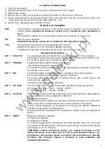
TO CHECK CONNECTIONS
1) Cut-off power supply.
2) Manually release the wing, move it to approx. half-stroke and lock it again.
3) Reset power supply.
4) Send a step-by-step control signal by pressing the button or the remote control key.
5) The wing should start an opening movement. If this is not the case, invert the movement wires (25< >27)
of the motor and the limit switch wires SWO-SWC (19< >20).
6) Adjust Time, Operating Logic and Motor Power.
FUNCTION OF TRIMMERS
ENC
The sensitivity to obstacle detection of the optical sensor is adjusted in both opening and
closing phases.
Adjustment should be carried out in compliance with regulations in
force
.
If an obstacle is detected, the movement is stopped and reversed for about 3 sec.
PW
Motor torque is adjusted.
Adjustment should be carried out in compliance with regulations in force.
TCA
The automatic closing time can be adjusted by this trimmer.
Adjustment ranges from
1
sec minimum to
90 sec
maximum.
To disable the automatic closure set the trimmer to the maximum value (+)
DIP-SWITCH FUNCTION
DIP 1 “SCA/II°ch”
The operating mode of the SCA/ II°ch output to terminals 17-18 is adjusted.
Off: Output is set as SCA (open gate indicator light) or as FotoTest if DIP5 is ON.
On: Output is preset as 2
nd
ch (second radio channel).
DIP 2 “PRELAM.”
Forewarning flashing light enabled or disabled.
Off: disabled forewarning flashing light.
On: enabled forewarning flashing light. The flashing light is activated 3 sec before
the starting of the motor.
DIP 3 “BLI”
The PP input (Step-by-Step) is enabled or disabled in the opening phase.
Off: During opening, all controls are regularly carried out.
On: During opening, the PP input is disabled. Hence, also controls sent by the
control unit are disabled.
The other inputs are therefore still active.
DIP 4 “P.P. Mod”
The “P.P. push-button” and the transmitter operating modes are selected.
Off: Operation: OPEN > STOP > CLOSE > STOP >
On: Operation: OPEN > CLOSE > OPEN >
DIP 5 “Test DM”
The FotoTest functions and the single fault control are activated or deactivated in
compliance with Directive on Machinery 98/37/CE.
Off: Disabled functions.
On: Enabled functions. Before any operation of the limit switches, the control unit
carries out a check of single failures and correct operation of photocells.
In case of faulty operation, no movement is carried out and LED DL1 flashes as
indicated in paragraph “LED Diagnostics”
Power the photocell transmitters (TX) through SCA outputs, as per wire diagram at
page 4.
DIP 6 “SLWD”
Braking is enabled or disabled.
Off: Braking is disabled.
On: Braking is enabled.
For motors equipped with optical sensor (encoder) and DIP7 only: ON. The control
unit carries out the final phase of the opening and closing movements at reduced
speed (approx. 70 cm of stroke).
“WARNING: external mechanical factors, e.g. weight and friction on the
sliding movement of the door leaf, as well as environmental factors, e.g.
temperature, and weather agents may affect the performance of braking.
Therefore, this functions requires a structure in good conditions and
adequate maintenance.”
www.ga
ł
ecki.pl
Summary of Contents for CP.MS4
Page 23: ...w w w g a e c k i p l...


