14
PoSItIonIng oF tHE SPrIng
AnD ACCESSorIES
FIg.6
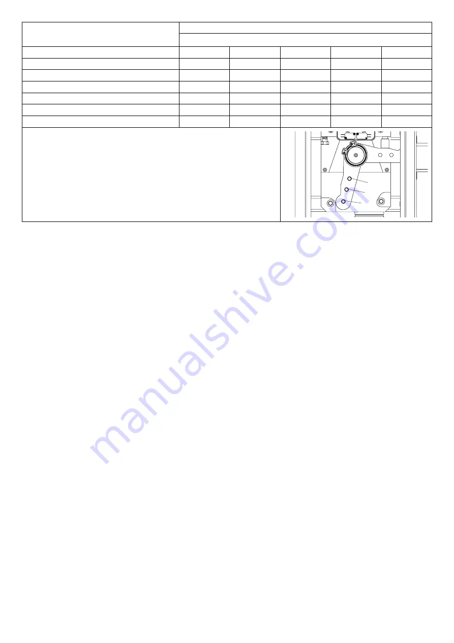
According to the length of the beam and the type of accesso-
ries installed, before tensioning the spring, the correct point
to hook the spring to the lever must be selected.
The correct hooking point (“A”, “B” and “C”), must be se-
lected by taking account of table 1, according to the beam
length and the type of accessories to be installed.
HoW to FIX tHE BEAM
FIg.7
Any accessories for the beam (protection edges, lights, pneu-
matic safety edges, rack, etc. ) are installed before fitting the
beam. See relevant instructions.
Fit the beam to plate P by using bracket S and both the 6
screws with the corresponding washers, and plate T.
Apply the removable plastic cover C.
EMErgEnCY MAnuAL oPErAtIon
FIg.8
Should a power failure occur or in the event of faults in the
system, the beam can be released and moved by hand:
• Introduce the customized key in the release lever and turn
it clockwise.
• Turn the release lever anti-clockwise until the beam is
released and it can be opened and closed by hand.
• To reset the automatic operation, turn the lever clockwise
until the beam is released. Reset the initial position.
BALAnCIng
FIg.9
For a good operation of the road barrier, the beam must be
suitably balanced by the spring.
To check the correct balancing, proceed as follows.
• Check that the spring is correctly hooked to the lever (see
table 1).
• Mechanically release the road barrier through the release
key.
• The road beam, correctly balanced, should remain still in
tAB.1
EVA.5
Bar length (m)
Accessories for use
3
3,5
4
4,5
5
EVA5.A
C
C
B
B
A
EVA5.A + VE.RAST
C
B
B
A
A
EVA5.A + VE.AM
C
C
B
B
A
EVA5.A + VE.RAST + VE.AM
C
B
B
A
A
EVA5.A + SC.RES
C
B
B
A
A
EVA5.A + SC.RES + VE.AM
C
B
B
A
A
Key
EVA5.A
Shank with rubber and upper profile.
VE.rASt
Aluminium skirt.
VE.AM
Mobile support for bar.
SC.rES
Sensitive resistive edge (complying with annexe 4
of the Machines Directive).
Attention:
The installation of the
VE.rASt
interferes with the use of the
SC.rES
and vice
versa.
The installation of the
EVA.L
lights kit does not influence the balancing of the bar
any position:
- if it tends to open, reduce the spring tension
- if it tends to close, increase the spring tension
The spring tension can be adjusted by tightening (anti-
clockwise rotation) or loosening (clockwise rotation) the
spring by hand. Once the spring tension is adjusted, lock
it by moving the nut “D” in contact with cap T.
MoVEMEntS AnD oPErAtIng tIME
During opening as per Fig. 10:
Starting from the closing position “C”, the beam starts its
opening until it reaches the “SWO-R” point, where the ope-
ning limit switch triggers. The opening speed can be adjusted
through the control unit.
The beam moves for the remaining space (as shown in Fig.10)
at a reduced speed, for a time preset by the control unit.
Therefore, the barrier reaches point A, by completing the
opening movement.
During closure, as per Fig. 11:
The beam starts moving from the opening point “A” and stops
at “SWC-R “ point, when the braking limit switch triggers. The
closing speed can be preset through the control unit.
After activation of the braking limit switch, the braking cycle
starts, ending only when the closing limit switch “C” trig-
gers.
The control unit checks the activation of the “SWC” limit
switch and it is able to automatically offset any changes due
to different weather conditions, for example.
The braking angle shown in Fig.11 is fixed at around 25°.
Adjustments of the limit switch cams, trimmers and dip-
switches should be carried out by referring to these operating
principles.
ADJuStMEnt oF LIMIt SWItCH CAMS
FIg.13
The adjustment of the limit switch cams allow for the fol-
lowing:
Cam o
To advance or delay the starting of braking in the opening
C
B
A
Summary of Contents for EVA 5
Page 2: ...2 1 A A 3 D 2 EVA 5 SX EVA 5 DX 320 330 235 1200 Min 2 75m Max 4 75m 250...
Page 3: ...3 4 F1 F2 F1 F2 L L...
Page 5: ...5 8 9 D T CLACK...
Page 6: ...6 10 12 11 SWO R A C A SWC R C SWC SWO R SWC R SWC O C V...
Page 7: ...7 13 G 14 F1 F2 2 9x16 FTC S 3 1 2 4 4 5 6 7 3x1 5mm 2x1mm...
Page 40: ...AUTOMATISMI BENINC SpA Via Capitello 45 36066 Sandrigo VI Tel 0444 751030 r a Fax 0444 759728...


