


22
5) LEFT-RIGHT BARRIER (FIG. 3/4)
The EVA.8 normally is provided as right barrier (Fig. 3 A : EVA.8 RIGHT)
Conventionally it is considered right a barrier which seen from the side of the cabinet door, closes the passage by lowering the boom towards right.
However it is possible to reverse the barrier movement and turn a right barrier into a left one by means of few easy operations (Fig. 3 B : EVA.8 LEFT).
If the opening direction reversion is required, proceed as follows. If it is not necessary, go to the next section:
• totally unload the springs by loosening them and unhook them from the anchoring lever “L” (fig. 4)
• remove screws D1 and D2 and fix the extension rod A in the opposite position, on lever V.
• remove and fix the extension lever R in the opposite position.
• fix the springs onto the anchoring lever “L” .
• Fig. 4 shows the different positions of the components shows the differences between a right-hand road barrier and a left-hand one.
ATTENTION: AN INVERSION OF THE OPENING DIRECTION IMPLIES THE MODIFICATION OF THE POS MENU, AS DESCRIBED IN THE
PARAGRAPH “PROGRAMMING OF THE CONTROL UNIT”.
6) EMERGENCY MANUAL OPERATION (FIG.5)
Should a power failure occur or in the event of faults in the system, the beam can be released and moved by hand:
• Introduce the customized key in the release lever and turn it clockwise.
• Turn the release lever anti-clockwise until the beam is released and it can be opened and closed by hand.
• To reset the automatic operation, turn the lever clockwise until the beam is released. Reset the initial position.
7) INSTALLATION OF THE OPTIONAL FOUNDATION PLATE VE.P650 (FIG.6)
After preparing the cable laying (mains power supply, accessories, etc.), place the foundation plate keeping to dimensions indicated.
Brackets to be cemented are supplied with the VE.P650 plate (ref. S). The brackets must be fitted to the foundation plate by means of 4 screws M12x50 (ref. V).
Check that the foundation plate is perfectly flat (ref. L), then fix the road barrier by means of nuts D and corresponding washers R.
Notes: the special shape of the slots on the bottom of the barrier cabinet, allow to adjust finely the position of the barrier.
It is suggested to leave 30 mm of threaded bar out from the foundation plate, a bigger length could generate an interference with the spring, a smaller
length does not ensure the proper fixing of the barrier.
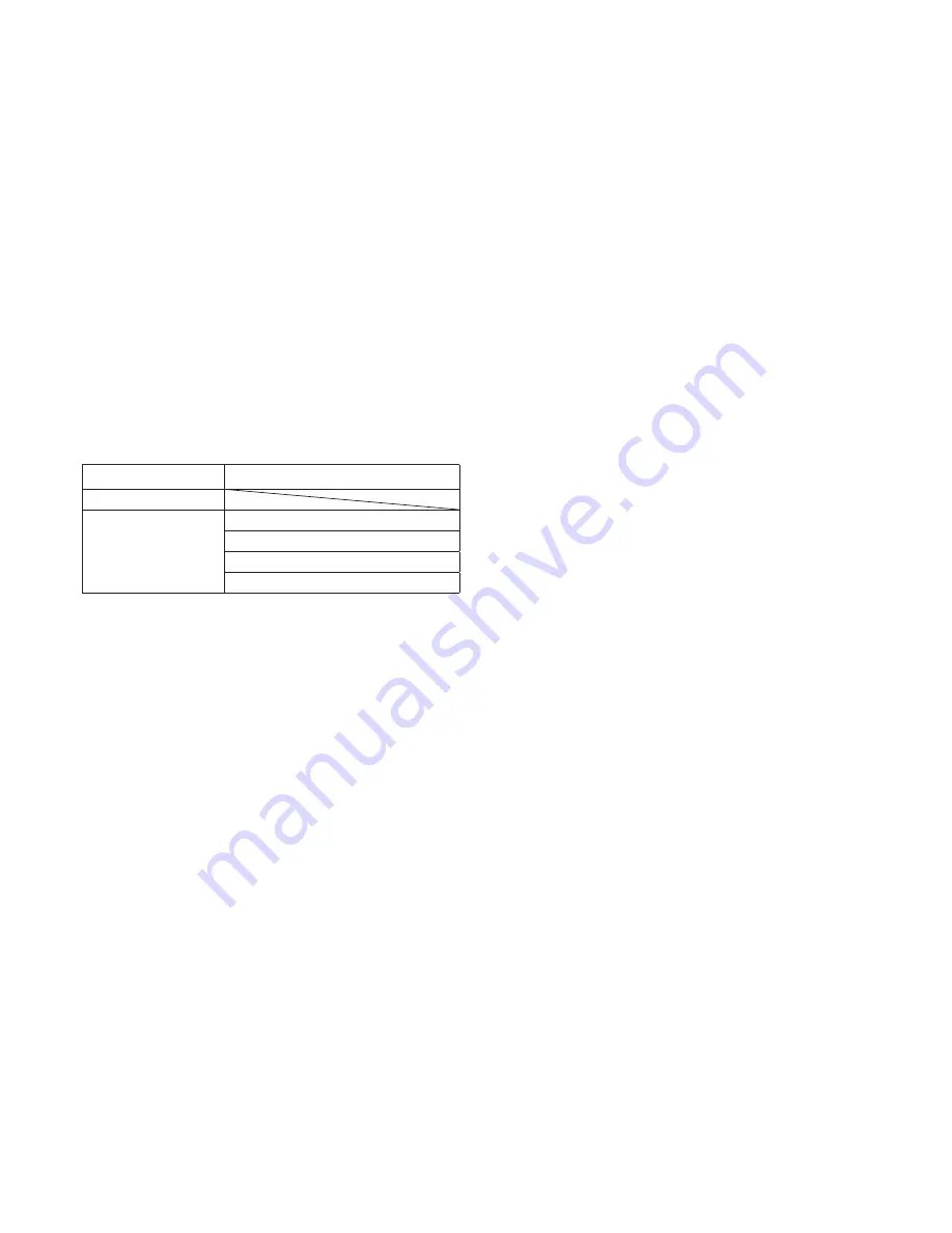
8) SELECTION OF ACCESSORIES
ROD LENGTH
USABLE ACCESSORIES
8 m
7 m
VE.RAST
SC.RES
VE.RAST + VE.AM
SC.RES + VE.AM
9) HOW TO FIX THE BEAM (FIG.7)
Any accessories for the beam (protection edges, lights, pneumatic safety edges, rack, etc. ) are installed before fitting the beam. See relevant instructions.
Fit the beam to plate P by using bracket S and both the 6 screws with the corresponding washers, and plate T.
Apply the removable plastic cover C.
10) BALANCING (FIG.10)
For a good operation of road barrier, the beam must be suitable balanced by the spring.
To check the correct balancing, proceed as follows:
• Mechanically release the road barrier through the release key.
• The road beam, correctly balanced at approx. 45° , should remain still in any position:
- if it tends to open, reduce the spring tension
- if it tends to close, increase the spring tension
The spring tension can be adjusted by tightening (anti-clockwise rotation) or loosening (clockwise rotation) the spring by hand. Once the spring tension
is adjusted, lock it by moving the nut “D” in contact with cap T.
11) HOW TO ADJUST THE MECHANICAL STOPPERS (FIG.13)
After the motor stop, the inertial movement of the beam is blocked thanks to adjustable mechanical stoppers.
By taking Fig.11 as a reference:
• Loosen locking screws V1 and V2.
• Tighten/loosen the mechanical stoppers F1 and F2 until the desired activation position is obtained.
• Fix screws V1 and V2.
12) WIRE DIAGRAM (FIG.14)
This figure shows an installation example of road barrier with its main accessories.
KEY
1. Control unit CP.EVA2
2. Receiver photocell FTC.S
3. Transmitter photocell FTC.S
4. Emergency batteries that can be installed inside the container of the control unit DA.BT2
5. EVA.LAMP flashing light card
6. Safety edge resistive type (8K2)
7. Control unit for safety edge management SC.EN
8. Blinking lights LADY.L
To install and connect the various accessories, see related instructions.


