


37
18) NOTSTROMBATTERIE
Das Steuergerät CP.LADY umfasst die Netzteilkarte SA.24V, die den eventuellen Anschluss zweier Batterien 12V 2,1 Ah DA.BT2 (Optional) vorsieht.
Dadurch ist der Betrieb der Automation auch bei zeitweiligem Stromnetzausfall möglich.
Beim normalen Netzbetrieb lädt die Karte SA.24V die Batterien wieder auf (Abb. 13).
Der maximale Ladestrom beträgt 1 A, der durchschnittliche Wert 300 mA.
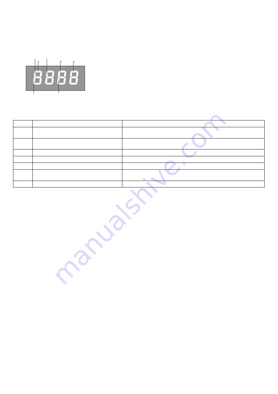
19) DIAGNOSE
PHOT
SW Close
STOP
SW Open
P.P.
OPEN
CLOSE
LED 1: Netzstrom vorhanden
LED 2: Steuergerät CP.LADY korrekt mit Strom versorgt
Jedem Eingang ist ein Displaysegment zugeordnet, das sich bei einer Aktivierung einschaltet und
dabei nachstehendem Schema folgt.
Die senkrechten Segmente stellen die N.C. Eingänge dar.
Die waagrechten Segmente stellen die N.O. Eingänge dar.
Der Blinkmodus der Segmente SW Open (bei offener Schranke) und SW Close (bei geschlossener
Schranke)
20) FEHLERMELDUNGEN
Im Folgenden werden einige Meldungen aufgelistet, die auf dem Display bei Betriebsstörungen angezeigt werden:
Err
Allgemeiner Fehler
Fehler Passworteingabe, Speicherung Sendegeräte.
Err1
Fehler Motor
Die Motoranschlüsse überprüfen, Motor nicht angeschlossen oder nicht funktions-
tüchtig, Problem an der Steuerung.
Err2
Fehler Lichtschranken
Anschlüsse und Ausrichtung der Lichtschranke überprüfen oder Hindernisse vor-
handen.
err3
Fehler Absolut-Encoder
Anschlüsse des Encoders überprüfen, seinen Betrieb prüfen.
AMP
Sensor Kraftabschaltung ausgelöst
Das Vorhandensein von Hindernissen oder Reibung prüfen.
THRM
Temperatursensor ausgelöst
Überhitzung bei übertriebenem Dauerbetrieb, Rückstellung abwarten.
OVLD
Überlast
Überschreitung der Höchstleistung. Motor prüfen oder nachsehen, ob Reibungen
vorliegen.
Enc
Encoder
Empfindlichkeit des Encoders.
Summary of Contents for LADY 5
Page 5: ...5 8 G F G F D T 7 ...


