


16
17
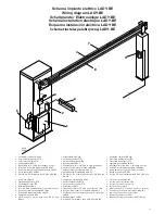
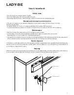
Warnings and advice for installation
Before carrying out any work on the system, disconnect the 230Vac and the buffer batteries (if
present).
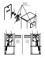
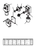
• The box containing the control unit is secured to barrier case with two screws to avoid damage during trans-
port. Once the barrier has been positioned it possible to remove the screws and to unhook the box from the
case so as to facilitate wiring operations and the preparation of the control unit. On completing installation,
secure the box to the barrier case again.
• Although it is possible to invert the barrier opening direction, it is advisable to consider beforehand the direc-
tion of the barrier necessary for the type of installation and to use a barrier prepared by the manufacturer.
• Consult the control unit instructions manual as regards the regulation of the operating times and logic, the
connection of the accessories and of the safety devices, etc.
1. General characteristics
Sturdily made but with a sober and pleasing design, LADY-BE road barriers are suitable for intensive use, thanks
to their 24Vdc motor. Installation and regulation are easily accomplished. Equipped with a very simple and
intuitive manual release, the barrier can be fitted with buffer batteries that allow it to operate even when there
is no power supply.
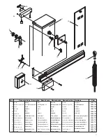
The bar made of painted aluminium is suitable for the application of all the accessories, signalling and safety
devices. In the event of contact of the bar with an obstacle, an amperometric sensor interrupts the movement
immediately.
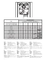
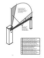
2. Positioning the spring and the accessories for use
Depending on the length of the bar and on the type of accessories installed, before putting the spring under
tension it is necessary to choose the correct point in which to attach the spring to the lever.
The correct fastening point (“A”, “B” or “C” - Fig.1), must be chosen in table 1, depending on the length of the
bar and on the type of accessories you intend to install.
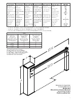
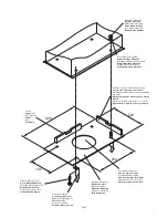
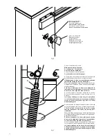
3. Laying the foundation plate (Fig.2)
After having arranged the passage of the cables (power supply, accessories, etc.), put the foundation plate in
position, referring to the measurements in fig.2.
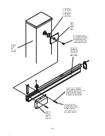
4. Fixing the bar (Fig.3)
The bar is fixed to the plate using the support and the screws provided, as illustrated in Fig.3. We recommend
installing any accessories for the bar (protective profiles, lights, edge, skirt, etc.) before fixing it to the plate.
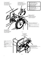
5. Preparing the barrier for right or left
The LADY-BE barrier is available in versions for either right-hand or left-hand operation.
A right-hand barrier is one which, viewed from the side of the door, occupies the passage on the right-hand side;
vice versa the left-hand version. If necessary, it is possible to transform a right-hand barrier into a left-hand one
(or vice versa). Proceed as follows (Fig.4):
• unload the spring completely, unscrewing it, and unhook it from the anchoring lever “L”
• remove the limit stop disk “F”
• unscrew the blocking ring nut “G”
• remove the spring anchoring lever “L” and reposition it in the opposite position to the one occupied previ-
ously
• check the timing (alignment) between the fixing plate “P” and the anchoring lever “L”
• invert the position of the mechanical stops “F1” and “F2”. Slacken the respective blocking dowels before
unscrewing the stops (see paragraph 9).
• fasten the spring in the new position; Fig. 5 shows the differences between a right-hand barrier and a left-
hand barrier.
• in the control unit, invert the motor connections and the limit stops SWC (closing limit stops) and SWC-R
(closing slowing limit stop).
6. Manual and emergency manoeuvres
In the event of a power cut or of abnormal operation, it is possible to release the bar and move it by hand (Fig.
6).
Using the key provided:
• To release the bar, turn the key in a clockwise direction until you fell a certain resistance.


