background image

10

11

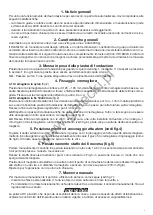
1. General information

For an efficient operation of the sliding automatic mechanism, the gate must have the following features:
-  The guide rail and its wheels must be suitable in size and mantained to prevent gate from excessive sliding 

friction.

-  When running, gate must not rock excessively.
-  Opening and closing stroke must be regulated by a mechanical limit stop (to safety standard in force).

2. General features

Automation for private use sliding gates (max. gate weight 600Kg).
The small and elegant design enbloc RI.6MLS consists of a painted aluminium unit containing the motor and 
irreversible reduction unit, realized with high-grade materials. The reduction parts are completely immersed 
in oil. The RI.6MLS is equipped with magnetic limit switches

.


A personalized key emergency release enables manual gate operation in the event of power failure.

3. Foundation slab laying

Secure the foundation slab to the ground with no. 4 steel T pressure inserts  to dimensions given in fig. 1 (it’s 
important the slab is securely fastened to the ground).
N.B.: Go through holes F with a sheath suitable to the actuator feed cables.

4. Rack fixing

4.1 Nylon rack (fig. 2)

Place the rack at a height of 125 ÷ 126 mm from the base of the foundation slab up to the rack tooth head; 
drill and thread M6 the gate approx. in the center line between the rack slots. Now secure the rack and refer 
to points 4.3 and 4.4 before proceeding.

4.2 Fe 12x30 mm rack (fig. 2)

Weld or screw the spacer pins D onto the gate at 144 ÷ 145 mm above the base of the foundation actuator 
slab and maintain the same pitch as the rack drilling. Now secure the rack and refer to points 4.3 and 4.4 
before proceeding.

4.3

 Keep the pitch of teeth  between the two parts of the rack; the joining with another piece of rack would 

make it easier to achieve (see fig. 2)

4.4 

Secure the rack with the screws V making sure, once the actuator has been installed, that between rack 

and the drive gear there is always approx. 1 mm clearance (see fig. 3); to get this clearance use the slots on 
the rack.

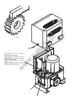
5. Actuator positioning and fixing (see fig. 4)

Remove the case by untightening the screws V. Place the actuator unit so that the gear is centered to the 
rack; level it with the grains G and if necessary adjust the clearance between rack and gears (according to 
fig. 3). Now tighten the screws L.

6. Limit stop flask positioning (see fig. 5)

Open manually the gate and leave approximately of 1÷3 cm, depending on gate weight, between gate and 
positive mechanical stop A.
Using the dowels provided, secure the limit switch bracket as shown in Fig. 5, in reversed position, so that 
the bracket will not stick out of the rack.
Position the magnet to the bracket and after you have located the sensor’s switch point, secure the magnet 
to the bracket with a screw. The gap between magnet and sensor should not exceed 20mm (Fig.6).
Repeat the procedure with door closing. 

7. Manual operation

To operate the gate manually, use the release as follows (see fig. 7):
-  once inserted the personalized key C, turn it anticlockwise and pull the lever L.
-  to reset the standard operation running, close the lever L and operate the gate manually, until engage-

ment.

CAUTION

The civil liability policy, which covers possible injuries to people or accidents caused by defects in construction, 
requires the system to be to existing standard and to use original Benincà accessories.

www.ga

ł

ecki.pl

Summary of Contents for RI.6MLS

Page 1: ... PARA CORREDERAS ELEKTROMECHANICZNY POSUWOWY OTWIERACZ BRAM Libro istruzioni e catalogo ricambi Operating instructions and spare parts catalogue Betriebsanleitung und Ersatzteilliste Livret d instructions et catalogue des pieces de rechange Libro de instrucciones y catálogo de recambios Książeczka z instrukcjami i katalog części wymiennych UNIONE NAZIONALE COSTRUTTORI AUTOMATISMI PER CANCELLI PORT...

Page 2: ... dichiarazione non formi un complesso unico con la macchina finale Benincà Luigi Responsabile legale Sandrigo 01 06 2007 Declaration by the manufacturer Directive 89 392 EEC Art 4 2 and Annex II sub B Divieto di messa in servizio Manufacturer Automatismi Benincà SpA Address Via Capitello 45 36066 Sandrigo VI Italia Herewith declares that the operator for sliding gates model RI 6MLS is intended to ...

Page 3: ...inie in nationales Recht entspricht und die entsprechende Konformitätserklärung ausgestellt ist Benincà Luigi Responsabile legale Sandrigo 01 06 2007 Declaration du fabricant Directive 89 392 CEE Article 4 2 et Annex II Chapitre B Interdiction de mise en service Fabricant Automatismi Benincà SpA Adresse Via Capitello 45 36066 Sandrigo VI Italia Déclaire ci apres que l automation pour grilles couli...

Page 4: ...n conjunto único con la máquina final Benincà Luigi Responsable legal Sandrigo 01 02 2003 Deklaracja UE o zgodności z normami dla maszyn Wytyczna 89 392 UE Załącznik II Część B Zakaz użytkowania Producent Automatismi Benincà SpA Adres Via Capitello 45 36066 Sandrigo VI Italia Oświadcza że Automatyzm do bram przesuwnych model RI 6MLS został opracowany z myślą o wbudowaniu go do maszyny lub zmontowa...

Page 5: ...ax Öffnungsgeschwindigkeit Kondensator Schmierung Gewicht Masse Alimentation Puissance Absorption Couple Rapport de reduction Classe d isolement Interv protect therm Temp fonctionnement Poids max portail Vitesse d ouverture Condensateur Lubrification Poids Dimensions Alimentación Potencia Absorción Par Relación de reducción Clase de aislamiento Interv termoprotección Temp funcionamiento Peso máx d...

Page 6: ... level Senkrecht gegenüber der Zahnstange positionieren und ausrichten Réglage en hauteur par rapport à la cremaillére et mise en niveau horizontal Posicionar en altura con respecto a la cremallera y apretar Umieścić na wskazanej wysokości względem zębatki i ułożyć w pozycji poziomej V L G w w w g a ł e c k i p l ...

Page 7: ...chiebegitters gegen den Endschalter A erfolgen kann N B L étrier de fin de course doit être positionné de façon à pouvoir arrêter le portail sans qu il aille bûter sur le fin de course mécanique NOTA La pletina del final de carrera debe ser colocada de tal forma que permita la parada de la cancela sin que ésta vaya a tocar con el tope mecánico Uwaga Zaczep krańcówki musi być w pozycji takiej by mo...

Page 8: ...SC ou ID SCE 7 Feu clignotant ID LUX 8 Antenne LO E1N Leyenda 1 Motorreductor con centralita incorporada 2 Cremallera 3 Pletinas de los finales de carrera 4 Fotocélulas SC P50 de empotrar SC P50E de superficie 5 Topes mecánicos 6 Selector a llave o teclado digital ID SC o ID SCE 7 Relampagueador ID LUX 8 Antena LO E1N Objaśnienia 1 Siłownik z centralką wbudowaną 2 Zębatka 3 Zawieszki wyłączników p...

Page 9: ... dalla piattaforma su cui andrà fissata la piastra di fondazione dell attuatore e ad un passo pari alla foratura sulla cremagliera Fissare infine la cremagliera rispettando i punti 4 3 e 4 4 4 3 Rispettare il passo di dentatura anche tra uno spezzone di cremagliera e l altro a tale scopo può essere utile accoppiare un altro spezzone di cremagliera vedi fig 2 4 4 Fissare infine la cremagliera con l...

Page 10: ... Now secure the rack and refer to points 4 3 and 4 4 before proceeding 4 3 Keep the pitch of teeth between the two parts of the rack the joining with another piece of rack would make it easier to achieve see fig 2 4 4 Secure the rack with the screws V making sure once the actuator has been installed that between rack and the drive gear there is always approx 1 mm clearance see fig 3 to get this cl...

Page 11: ...zwischen der in der Zahnstange gefräste Nuten entsprechen Die Zahnstange entsprechend den Punkten 4 3 und 4 4 befestigen 4 3 Die Zahnteilung zwischen den Zahnstangenstücken muß außerdem eingehalten werden zu diesem Zweck wäre es nützlich ein zweites Zahnstangenstück zu paaren siehe Bild 2 4 4 Durch die Schrauben V die Zahnstange befestigen bitte beachten daß nach der Installation des Ak tuators ei...

Page 12: ... fondation du motoréducteur et au même pas que celui de la cremaillére Ensuite fixer la cremaillére en respectant les points 4 3 et 4 4 4 3 Respecter le pas de denture même dans le cas de 2 morceaux de cremaillére pour cela il est conseillable d adapter un autre morceau de cremaillére voir fig 2 4 4 Visser la cremaillére avec les vis V en ayant soin lorsque le motoréducteur est installé de laisser...

Page 13: ... 144 145 mm de la plataforma sobre la qual se fijará la plancha de fundición del operador y haciéndolos coincidir con el agujereado de la cremallera Fijar finalmente la cremallera respetando los puntos 4 3 y 4 4 4 3 Respetar el paso de los dientes también entre una y otra pieza de la cremallera a tal fin puede ser útil acoplar otra pieza de cremallera véase fig 2 4 4 Fijar finalmente la cremallera...

Page 14: ...rej zamocowana będzie płyta fundamentowa siłownika i w odstępie jednego posuwu od otworu na zębatce Zamocować zębatkę zgodnie ze wskazówkami w punktach 4 3 i 4 4 4 3 Przestrzegać posuwu uzębienia również pomiędzy jednym a drugim przedziałem zębatki w tym celu pomocne może być dołączenie dodatkowego przedziału zębatki zob Rys 2 4 4 Zamocować wreszcie zębatkę za pomącą śrub V pamiętając aby po zamon...

Page 15: ... sblocco Release lever Hebel Levier Pal de desbloq Dźwignia odrygl 9686033 6 Piastra base Foundat plate Fundamentplatte Plaque fondat Placa de fundac Płyta podstawy 9686031 7 Albero uscita Output shaft Antriebszapfen Arbre Eje de salida Wał wyjściowy 9686028 8 Ingranaggio Gear Zahnrad Engrenage Piñon Koło zębate 9686032 9 Trasformatore Transformer Transformator Trasformateur Trasformador Transform...

Page 16: ...AUTOMATISMI BENINCÀ SpA Via Capitello 45 36066 Sandrigo VI Tel 0444 751030 r a Fax 0444 759728 w w w g a ł e c k i p l ...

Reviews: