background image

8

9

WARNING

• Before proceeding to installation, carefully read the following instructions:
• Do not use this component for purposes or applications different from those for which it is expressly studied 

and intended.

• If the unit is repaired and/or serviced, use only original components.

1. Use limits

The safety edge SC.RES can be used as a safety device for motorised doors and gates. Perpendicular op-
erating force: 50N.
Operating force at 45°: 350N.
This item can operate outdoor and at an ambient temperature ranging from –10° to +50° with a relative max 
humidity of 93%.
Max operating range: 50m.
N.B.: Do not put this product in contact with petrol, oils, solvents and acids.

2. assembly and sealing procedure

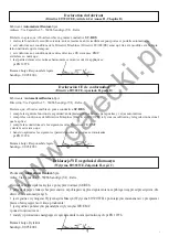
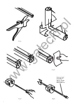
1)  Cut the edge at the desired length (fig. 1).
2)

  For item SC.90 only:


Cut the edge at 45°, possibly using the special scissors (item SC.F).


Insert the “L” nails to create continuity with “C” conductors inserted in the rubber. Fit the “T” cap with 
glue on the two edge ends (Fig. 2).

3)  To correctly insert the closing cap the base of the edge should be cut for 12 mm. The cut should be ac-

curate to endure a perfectly smooth surface (Fig. 3).

4)  Clean the indicated part with abrasive paper (Fig. 4).
5)  The closing cap features four pre-formed holes. Choose the desired hole to insert the cable and remove 

the plastic with a pointed tool (Fig. 5).

6)  Insert the cable through the hole (Fig. 6).
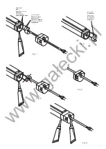
7)  Insert the needle contacts in the connector, as shown in the figure, axially positioned with respect to the 

wires in the rubber (Fig. 7).

8)  Insert the needle contacts of the resistance at the opposite end of the safety edge (Fig. 8).
 

N.B.: Before sealing the edge with the caps, check that the resistance at the end of the connecting cable 
is between 7.8 and 8.6 k

Ω

.

9)  Apply the adhesive tape on the clean surface of the edge and insert the cap immediately, then press on 

the cap for about 10 sec.


Important

: Apply the adhesive tape on the entire area described, proceeding as follows:


· Turn over the edge of the cap (Fig. 9)


· Apply the glue at the end of the safety edge and apply the cap (Fig. 10)


· Apply the glue on the rest of the surface, unfold the cap edge and make it adhere perfectly to the safety 
edge.


Warning

: the tip of the connector should be turned towards the outside (Fig. 10).

10)  To ensure the complete sealing, apply some glue around the edge of the cap and the hole used (Fig. 

11).

11)  For the closing cap at the other end of the safety edge, follow instructions given before the assembly of 

the resistance cap.

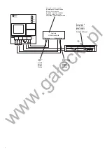
3. Wire connections

General characteristics of the unit for SC.RES
Power supply

: 24Vac ± 10% or 24Vdc ± 10%

Consumption

: max 60mA 

Output

: Normally closed contact

Input

: Line with 8.2kOhm ± 5% resistive terminal 

Status indicators


OK

: The input line is correctly provided with terminals. The output contact is closed.


O.C.

: The input line is open. The output contact is open.


S.C.

: The input line is short-circuited. The output contact is open.

Note: In case of power failure, the output contact is open.

www.ga

ł

ecki.pl

Summary of Contents for SC.RES

Page 1: ...te Livret d instructions et catalogue des pieces de rechange Libro de instrucciones y cat logo de recambios Ksi eczka z instrukcjami i katalog cz ci wymiennych UNIONE NAZIONALE COSTRUTTORI AUTOMATISMI...

Page 2: ...he following safety function anti crashing anti scissoring for automatic doors and gates it complies with the Machine Directive Directive 89 392 EC and following alterations as well as national laws r...

Page 3: ...unci n de seguridad antiaplastamiento anticorte para puertas y verjas autom ticas cumple las condiciones de la Directiva M quinas Directiva 89 392 CE tal y como modificada y la legislaci n nacional qu...

Page 4: ...4 1 2 Fig 3 Fig 4 Fig 5 Fig 6 Cavo di connessione Connecting cable Anschlusskabel C ble de connexion Cable de conexi n Kabel po czeniowy Fig 1 45 C L T 45 C Fig 2 w w w g a e c k i p l...

Page 5: ...res Eingebettete Leiter Fils noy s Hilos ahogados Przewody zanurzone Contatti ad ago Needle contacts Nadelkontakte Contacts aiguille Contactos de aguja Styki ig owe Resistenza Resistance Widerstand R...

Page 6: ...Entr e Entrada Wej cie Alimentazione Power supply Speisung Alimentation Alimentaci n Zasilanie Centrale unit di controllo Control unit control device Einheit Steuereinheit Centrale unit de contr le C...

Page 7: ...ita desiderata fig 6 7 Premere ed infilare i contatti ad ago del connettore nella direzione mostrata in modo assiale ai fili anne gati nella gomma fig 7 8 Inserire i contatti ad ago della resistenza a...

Page 8: ...ensibile dovesse essere rottamato si dovr provvedere allo smaltimento a seconda delle norme vigenti nel Paese di installazione 5 Manutenzione Astenersi assolutamente dal tentativo di effettuare ripara...

Page 9: ...acts in the connector as shown in the figure axially positioned with respect to the wires in the rubber Fig 7 8 Insert the needle contacts of the resistance at the opposite end of the safety edge Fig...

Page 10: ...l of the unit Disposal of the safety edge should be in compliance with regulations in force in the country of installation 5 Servicing Due to hazard risks it is mandatory not to attempt to repair the...

Page 11: ...ng f hren Abb 6 7 Die Nadelkontakte des Verbinders in die angegebene Richtung axial zu den im Gummi eingebetteten Leiter dr cken Abb 7 8 Die Nadelkontakte des Widerstandes in das andere Profilende ste...

Page 12: ...n Falls die sensible Kante verschrottet werden sollte die jeweils geltenden Vorschriften beachten 5 Wartung Auf keinen Fall Reparaturen selbst vornehmen dies k nnte zu Unf llen f hren Reparaturen nur...

Page 13: ...e fig 6 7 Appuyer et introduire les contacts aiguille du connecteur dans la direction illustr e de mani re axiale aux fils noy s dans la gomme fig 7 8 Introduire les contacts aiguille dans la r sista...

Page 14: ...ination conform ment aux normes en vigueur dans le pays d installation 5 Maintenance S abstenir imp rativement de toute tentative d effectuer des r parations sous risque de provoquer des accidents pou...

Page 15: ...7 Apretar e introducir los contactos de aguja del conectador en la direcci n mostrada axialmente con respecto a los hilos ahogados en la goma fig 7 8 Introducir los contactos de aguja de la resistenc...

Page 16: ...orde sensible es preciso proceder a eliminarlo conforme a las normas vigentes en el pa s de instalaci n 5 Mantenimiento Abstenerse terminantemente de intentar efectuar reparaciones ya que pueden incur...

Page 17: ...zdejmuj c zatyczk zamykaj c za pomoc punktaka rys 5 6 Wprowadzi i wpuszcza przez ustalone wyj cie kabel po czeniowy rys 6 7 Naciska iwsuwa stykiig owez czkiwewskazanymkierunku wspos bosiowydodrut wza...

Page 18: ...oddana do z omowania proces degradacji musi by zgodny z normami obowi zuj cymi w Kraku jej zainstalowania 5 Konserwacja Nale y absolutnie powstrzymywa si od pr b dokonywania napraw gdy podczas ich wyk...

Page 19: ...w w w g a e c k i p l...
Page 20: ...AUTOMATISMI BENINC SpA Via Capitello 45 36066 Sandrigo VI Tel 0444 751030 r a Fax 0444 759728 w w w g a e c k i p l...
Reviews: