


23
TERMINAL BLOCK M2
P.P.
Step by step
Input for step by step command (N.O. contact) .
CLOSE
Close
Input for close command (N.O. contact) .
OPEN
Open
Input for open command (N.O. contact), It is possible to connect a timer for programmed openings.
PHOT
Photocell
Input for photocells enabled during opening and closing phase (N.C. contact).
STOP
STOP
Input for STOP command (N.C. contact).
SWC
Closing limit switch
CLOSED limit switch input (NO contact)
SWO
Opening limit switch
OPEN limit switch input (NO contact)
COM
Common
Common for all the input commands and the limit switches .
AUX2
Auxiliary output AUX 2
Output with N.O. contact configurable by means of the logic AUX 2
BLINK
Blinker
Output 24Vdc 15W max. for flashing light connection.
TERMINAL BLOCK M3
ANT-SHIELD
Antenna
Connection for the antenna of the built in receiver (ANT-signal/SHIELD-shield).
In case of use
of an external
antenna it is necessary to remove the pre-cabled cable from the terminal ANT
AUX
Auxiliary output AUX 1
Output with N.O. contact configurable by means of the logic AUX 1
24V
24 Vdc
Accessory power supply 24Vdc 500 mA maximum
MOT
Motor
Motor connection: 24Vdc.
13) PROGRAMMING
The programming of the various functions of the control unit is carried out using the LCD display on the control unit and setting the desired values in
the programming menus described below.
The parameters menu allows you to assign a numerical value to a function, in the same way as a regulating trimmer.
The logic menu allows you to activate or deactivate a function, in the same way as setting a dip-switch.
13.1) TO ACCESS PROGRAMMING
1 -Press the <PG> button to enter the first Installation menu “INST”.
2 -Choose with <+> or <-> button the menu you want to select
3 - Press the button <PG>, the display shows the first function available on the menu.
4 - With the <+> or <-> button, select the function you want.
5 - Press the button <PG>, the display shows the value currently set for the function selected.
6 - With the <+> or <-> button, select the value you intend to assign to the function.
7 - Press the button <PG>, the display shows the signal “PRG” which indicates that programming has been completed.
13.2) PROGRAMMING NOTES
Simultaneously pressing <+> and <-> from inside a function menu allows you to return to the previous menu without making any changes. Hold down
the <+> key or the <-> key to accelerate the increase/decrease of the values.
Hold down the <+> key or the <-> key to accelerate the increase/decrease of the values.
After waiting 120s the control unit quits programming mode and switches off the display.
When the board is switched on, the software version is displayed for around 5 sec
The pre-set logic functions and parameters are made taking account of a typical installation.
14) PARAMETERS, LOGICS AND SPECIAL FUNCTIONS
The following tables describe the functions available on the control unit
14.1) INSTALLATION (
INST
)
MENU
FUNCTION
MIN-MAX-(Default)
MEMO
BOOM
Select the length of the boom installed on the barrier.
Value expressed in meter from 3m to 5m or from 7m to 8m
According to the selected boom length, the optimal value of speed will be set.
3/5 -7/8 (7-8)
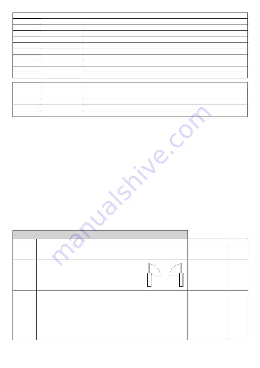
Pos
Set the closing direction of the barrier.
The symbol
0---
indicates right barrier (R/RIGHT) DEFAULT
The symbol
---0
indicates left barrier (L/LEFT)
Verify the opening direction of the boom and in case reverse it.
Every change of this function automatically implies the starting
of a new AUTOSET procedure.
RIGHT
(STANDARD)
LEFT
0---
= RIGHT
---0
= LEFT
( RIGHT )
Mode
Select the use mode of the barrier.
Norm
: Standard operating mode, for barriers used in a residential/industrial environment and
with normal traffic.
Parc
: Park operating mode, for barriers used in parking systems. In this mode, to promote
transit of a high number of vehicles, the control unit automatically sets a specific configuration
which includes:
1) Rapid closure enabled (SCL:ON) with time reduced from 3 to 0 seconds.
2) Automatic closure enabled (TCA:ON) which with rapid closure enabled causes, during the
opening phase, immediate closure of the barrier as soon as the PHOT input is free.
3) During the closure phase, PHOT entrance activation stops the barrier, as soon as the PHOT
input is free again, the barrier starts the closure manoeuvre.
Norm - Parc (Norm)


