background image

27

The logic LOC can be set in two ways:
ON: the SLAVE barrier can accept a local command and execute an opening/closing maneuver with no effect on the MASTER barrier.
OFF: the SLAVE barrier do not accept any local command and so it will replicate exclusively the behavior of the MASTER barrier.

A SLAVE barrier with LOC set to ON can be useful in case it is occasionally necessary the partial opening of a passage which is usually managed by two 
synchronized barriers, since that a step by step command (or OPEN/CLOSE) given to the SLAVE will have effect only on this last one, while all the other 
commands given to the MASTER will be replicated by the SLAVE.
The connection of the safety devices (photocells, safety edges, etc.) can be done indifferently to the MASTER unit or to the SLAVE.

16) TRANSMITTERS REMOTE LEARNING

If an already memorised transmitter is available in the receiver it is possible to carry out remote radio learning (without needing to access the control unit).

IMPORTANT: the procedure must be carried out with barrier open.The logic REM must be ON.

Proceed as follows:
1 Press the hidden key of the transmitter which is already memorised. 
2 Press, within 5s, the key of the corresponding transmitter which is already memorised to associate to the new transmitter. The flashing light will turn on. 
3 Press within 10s the hidden key of the new transmitter. 
4 Press, within 5s, the key of the new transmitter to associate to the channel chosen at point 2. The flashing light will turn off. 
5 The receiver memorised the new transmitter and immediately exits from programming. 

17) FUSES

F3 CP.LADY: T1A - Fuse for the protection of the accessories power supply
F1 SA.24V:    T4A - Fuse for general protection

18) BACK UP BATTERIES

The control unit CP.LADY includes the power pack SA.24V predisposed for the connection of two batteries by 12Vdc  2,1Ah DA.BT2 (optional) which 
guarantee the regular functioning of the automation in case of temporary power failure.
When the barrier is working with mains voltage the power pack SA.24V charges the batteries (Fig. 10).
The maximum charging current is 1A, the average charging current is 300 mA.
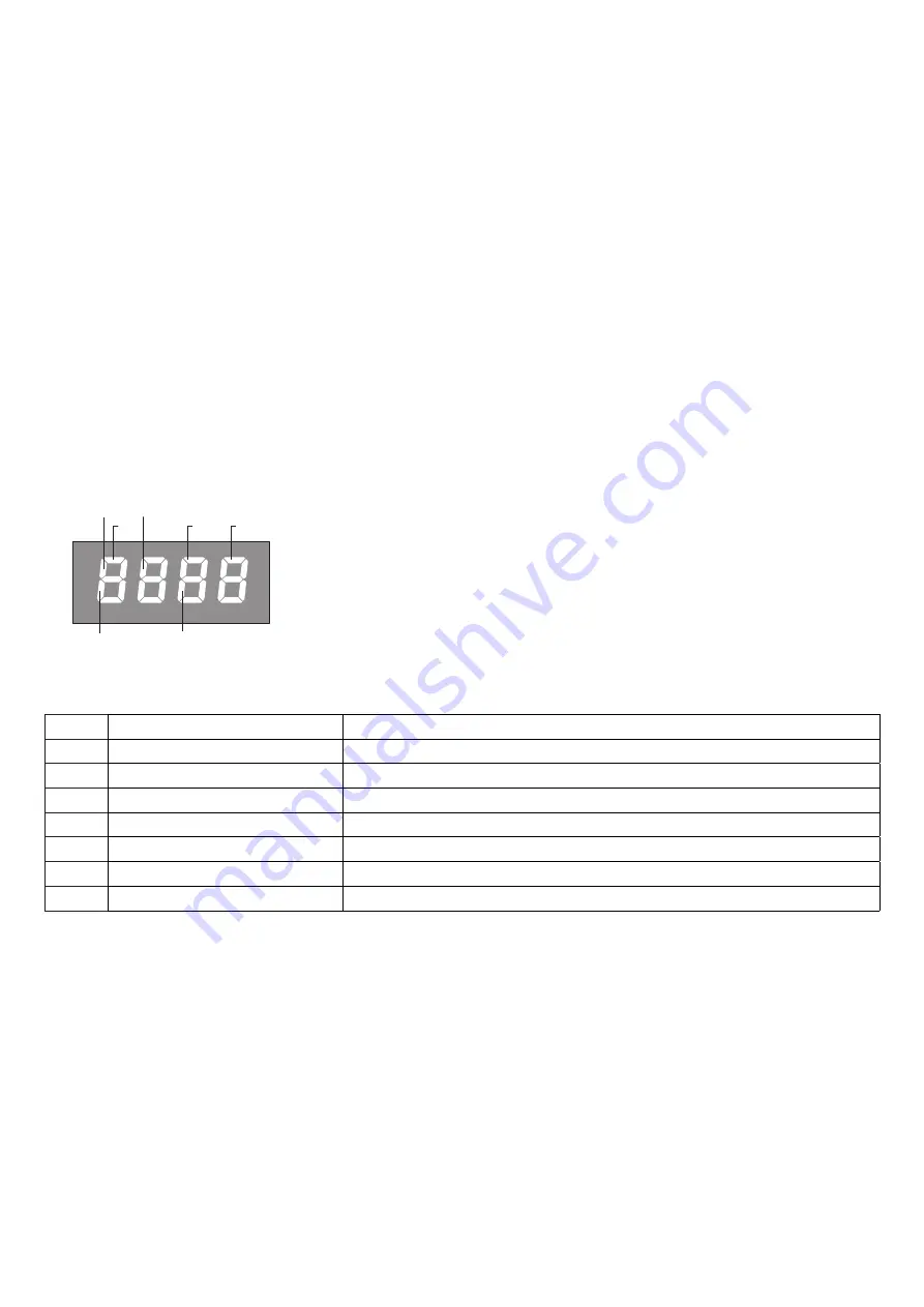
19) DIAGNOSTICS

PHOT

SW Close

STOP

SW Open

P.P.

OPEN CLOSE

LED 1 : Presence of mains voltage
LED 2 : Control unit CP.LADY correctly powered
To each input is associated a line of the LCD screen which in case of activation it turns on according to 
the following diagram.
The  N.C. inputs are represented by vertical lines. 
The  N.O. inputs are represented by horizontal lines.
The flashing mode of the lines SW Open (when the barrier is open) and SW Close (when the barrier is close) 

20) ERROR MESSAGES

Some messages that are displayed in case of function anomalies are listed as follows:

Err

Generic error

Error inserting password or memorizing transmitter..

Err1

Motor error

Verify the motor wirings, faulty motor or not connected, problem on the control unit.

Err2

Photocells error

Verify connections, photocells alignment and presence of obstacles.

err3

Absolute encoder error

Verify encoder connections, verify the good functioning of the Encoder.

AMP

Amperometric sensor intervention

Verify the presence of obstacles or friction points.

THRM

Thermal sensor intervention

Overheating due to a too intensive use, wait the restoring.

OVLD

Overload

Exceeding of the maximum power. Verify the motor and presence of friction points..

Enc

Encoder

Encoder threshold intervention.

Summary of Contents for VE.650

Page 1: ...L854200192 07 2020 rev 1 VE 650 UNIONE NAZIONALE COSTRUTTORI AUTOMATISMI PER CANCELLI PORTE SERRANDE ED AFFINI IT EN DE FR ES PL...

Page 2: ...3 1 M a x 6 5 0 m 35 300 1080 225 4 5 0 M a x 6 2 0 m A 460 170 255 310 F F A B C VE P650 OPTIONAL E D 2 3 P A C V...

Page 3: ...4 6 V T M D L 4 5 STANDARD...

Page 4: ...al stop for closing Mech Halt Schlie ung Arr t m canique fermeture Tope mec nico cierre Mechanizm zatrzymuj cy zamykanie D Dado tensionamento molla Spring tensioning nut Federspannmutter crou de mise...

Page 5: ...i na zwalnianie i zamnkni cia O Camma finecorsa apertura Opening limit stop cam Endschalternocken ffnen Came fin de course d ouverture Leva fin de carrera de apertura Krzywka kra c wki otwarcia Fineco...

Page 6: ...zelle vom Empf nger 4 Blinker VE L650 5 Pufferbatterien 2 Stck 12V 6 serienweise angeschlossen 6 Selektor 7 Druckregler SC PP 8 Pneum Anschlag SC P35 9 Grundplatte f r Batterien zusammen mit der Steue...

Page 7: ...RG PRG PRG PRG tca fsts sldo sldc tsmo pmo pmc pso psc seav sear 20 99 50 50 20 tsmc 20 20 20 20 0 0 TLS 60 saso 0 sasc 0 0 AUX1 PRG 2 AUX2 20 LOG RADI TCA tca IBL IBCA SCL PP PRE htr ltca tst1 tstm c...

Page 8: ...Die Taste PG dr cken Appuyez sur la touche PG Presionar la tecla PG Wcisn przycisk PG Premere simultaneamente e Press simultaneously keys and Gleichzeitig und dr cken Presser simultan ment et Presiona...

Page 9: ...ANT CLOSE P P U5 F3 MOT AUX 24V BLINK AUX2 COM SWO SWC STOP PHOT OPEN SHLD ANT CLOSE P P MOT AUX ANT M LAMP 24Vdc 24Vdc 500 mA CP LADY BAR LIGHT 24Vdc L LED 1 LED 2 F1 N SA 24V 100 250 Vac 2xDA BT2 Op...

Page 10: ...24Vac 24Vac COM NC NO RX TX 24Vdc COM AUX1 PHOT 24Vdc AUX1 AUX1 0004 tst1 on SCA PHOTOTEST AUX1 0000 AUX1 0003 24Vdc AUX1 SERVICE LIGHT L N 230Vac LAMP 24Vac LAMP Rel 24Vdc MASTER Menu BUS ID 0 SLAVE...

Page 11: ...ompleting installation secure the box to the barrier case again An omnipolar switch section switch with remote contact opening equal to or higher than 3mm must be provided on the power supply mains Ma...

Page 12: ...to that of normal rolling code transmitters with HCS coding but be aware that 1 ARC transmitters and Rolling Code HCS can not be stored in a single receiver 2 The first transmitter memorized determine...

Page 13: ...he unlocking lever is found inside the barrier column Lower the lever to release the shaft Bring the lever back to its original position to reset automatic movement of the shaft 10 MECHANICAL STOPS AD...

Page 14: ...o the function 7 Press the button PG the display shows the signal PRG which indicates that programming has been completed 13 2 PROGRAMMING NOTES Simultaneously pressing and from inside a function menu...

Page 15: ...ean contact 0 Open barrier light close contact when the barrier is open open contact when the barrier is close intermittent during the maneuver fig 11 SCA 1 Second radio cannel of the built in receive...

Page 16: ...ivated only with connected and operating emergency batteries On Activated function In the event of power failure the control unit causes an opening operation The barrier remains open until the power s...

Page 17: ...e typed in by using the numbers from 0 to 9 and the letters A B C D E F The default value is 0000 four zeros and shows the absence of a protection code While typing in the code this operation can be c...

Page 18: ...F3 CP LADY T1A Fuse for the protection of the accessories power supply F1 SA 24V T4A Fuse for general protection 18 BACK UP BATTERIES The control unit CP LADY includes the power pack SA 24V predispose...

Page 19: ...rection until it is blocked Maintenance Every month check the good operation of the emergency manual release It is mandatory not to carry out extraordinary maintenance or repairs as accidents may be c...

Page 20: ...62 7 2 3 4 5 6 1 Ref Code Note 1 9686556 2 968601519 3 96861520 4 9686107 5 9686109 6 7 968601521...

Page 21: ...15 15 I 13 14 11 12 16 16 I 17 18 19 Ref Code Note 9 9686120 10 9686160 11 9686116 12 9686118 13 9686115 14 9686117 15 9686114 15 I 9686318 16 9686113 16 I 9686316 17 9686119 18 9686666 19 968601410...

Page 22: ...AUTOMATISMI BENINC SpA Via Capitello 45 36066 Sandrigo VI Tel 0444 751030 r a Fax 0444 759728...

Reviews:

Related manuals for VE.650