Bennett 621 Interconnection Box Instruction & Service Manual
Installation Instructions
11
CONNECT RS485 COMMUNICATION WIRES
The following description is used for a RS485 payment communication. Field connections will depend on the Generic Current Loop Equipment
Available at the Site. Please read and understand other manufacturer information prior to installation. Refer to the
621 Wiring Diagram
(P2915) for
detailed information.
Note:
RS-485 wires should be twisted together no less than 3 turns per foot to reduce the effects of electrical noise on the
communication circuit. Due to the risk of noise, causing possible problems with communication, Bennett highly recommends
the use of twisted wires, but does not require it.
Note:
Belden shielded cable is accepted but the “drain” must not be
terminated.
1.
Connect 1 x 18ga. (+ positive) wire to the Fan Out Board at TS1, (+) positive as indicated on the diagram. Connect the other end to the 819/919
CPU Board at TS3, Terminal 1.
2.
Connect 1 x 18ga. (- negative) wire to the Fan Out Board at TS3, (-) negative as indicated on the diagram. Connect the other end to the
819/919 CPU Board at TS3, Terminal 3.
HOW TO START-UP THE 621 INTERCONNECTION BOX
Refer to the Diagnostics & Troubleshooting section for a detailed description and/or if an error occurs. If a problem occurs, refer to the service and
troubleshooting section for more information or call Bennett Technical Support at 1-800-423-6638.
1.
Apply power to dispensers, program them for operation, and address the fueling positions accordingly.
See “Helpful Programming Hints” on
page 12.
Refer to your dispenser operator’s manual or X19 technical and dispenser programming manual for detailed programming instructions.
2.
Apply power to POS, Site Controller, and Data Distribution Cabinet. Program and initialize POS as required.
See “Helpful Programming
Hints” on page 12
.
3.
Verify that the communication LED’s are flashing rapidly on the 621 board.
Refer to page 13 for Troubleshooting Diagnostics.
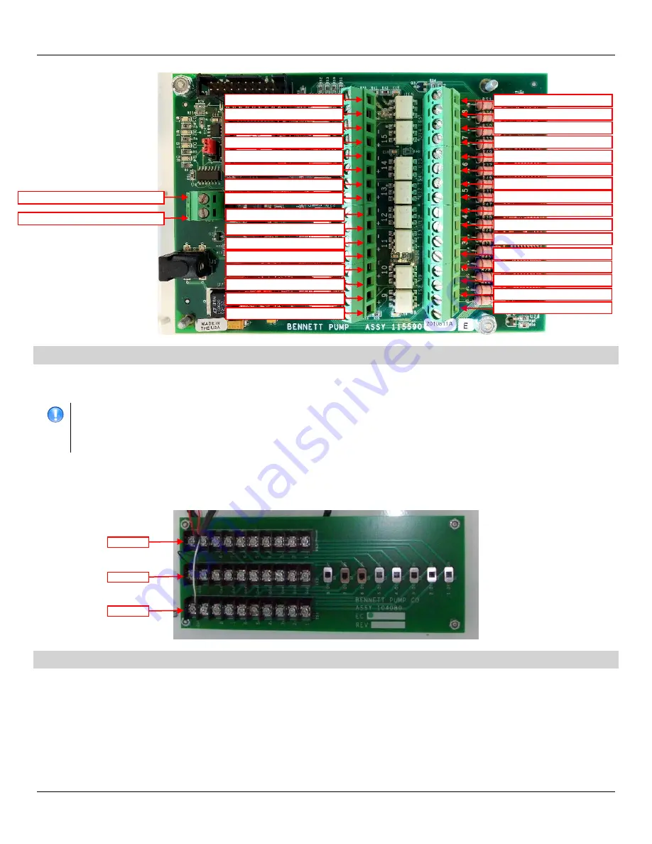
FUEL POSITION 17 & 18 (-) YELLOW
FUEL POSITION 17 & 18 (+) ORANGE
FUEL POSITION 19 & 20 (-) YELLOW
FUEL POSITION 19 & 20 (+) ORANGE
FUEL POSITION 23 & 24 (-) YELLOW
FUEL POSITION 23 & 24 (+) ORANGE
FUEL POSITION 21 & 22 (-) YELLOW
FUEL POSITION 21 & 22 (+) ORANGE
(-) YELLOW TO DATA DISTRIBUTION CABINET
(+) ORANGE TO DATA DISTRIBUTION CABINET
FUEL POSITION 1 & 2 (-) YELLOW
FUEL POSITION 1 & 2 (+) ORANGE
FUEL POSITION 3 & 4 (-) YELLOW
FUEL POSITION 3 & 4 (+) ORANGE
FUEL POSITION 5 & 6 (-) YELLOW
FUEL POSITION 5 & 6 (+) ORANGE
FUEL POSITION 7 & 8 (-) YELLOW
FUEL POSITION 7 & 8 (+) ORANGE
FUEL POSITION 9 & 10 (-) YELLOW
FUEL POSITION 9 & 10 (+) ORANGE
FUEL POSITION 11 & 12 (-) YELLOW
FUEL POSITION 11 & 12 (+) ORANGE
FUEL POSITION 13 & 14 (-) YELLOW
FUEL POSITION 13 & 14 (+) ORANGE
FUEL POSITION 15 & 16 (-) YELLOW
FUEL POSITION 15 & 16 (+) ORANGE
NOT USED
NOT USED
NOT USED
NOT USED
NOT USED
NOT USED
NOT USED
NOT USED
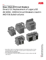
(-) NEGATIVE
RETURN
(+) POSITIVE


