Bennett 621 Interconnection Box Instruction & Service Manual
Product Introduction
7
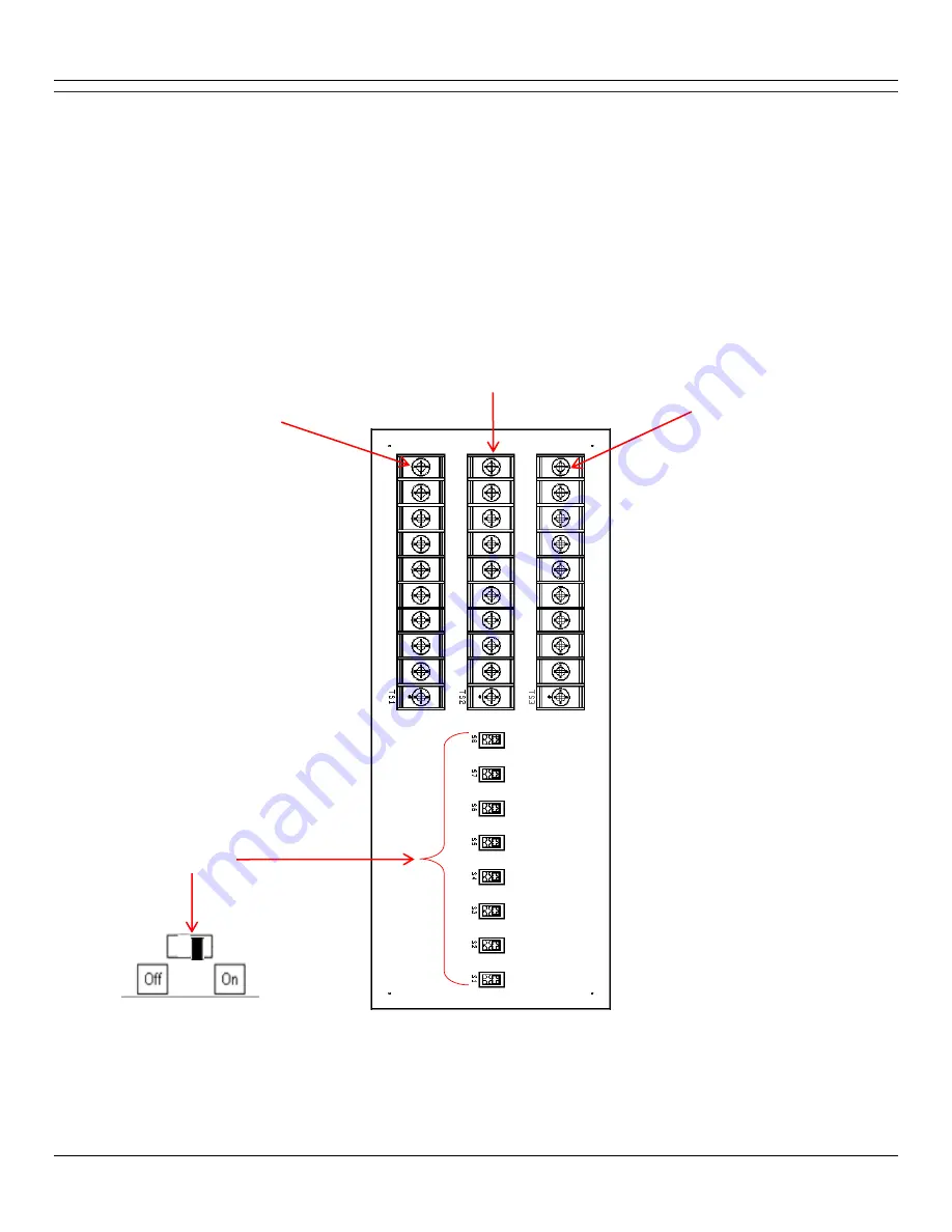
FAN-OUT CIRCUIT BOAR D
The Fan-Out Circuit Board in the Bennett Interconnect Box provides a connection to the dispenser’s payment module. The Fan-Out Circuit Board
has three sets of 10-position screw terminal strips.
TS1 connects the DATA (+) Positive for each dispenser.
TS2 connects the DATA Return for each dispenser. (If Required by Interface)
TS3 connects the DATA (-) Negative for each dispenser.
The board also provides switches for diagnostic purposes.
Note:
All switches must be in the
ON
position. If one of the switches is in the
OFF
position the point-of-sale will not be able to communicate to the dispenser connected to that DATA loop.
The Debit/Credit Terminal’s connect to the Fan-Out Board. One bad card reader terminal has the potential to take down the entire card system
since they are all in a common parallel loop. The switches are used to remove a suspected "bad" terminal from this data loop. Turning a switch off
will actually remove two terminals (one dispenser) from the data loop. This should help facilitate troubleshooting down to a particular dispenser.
TS3
Data (-) Negative
Switches 1 -8
NOT USED
TS1
Data (+) Positive
TS2
Data Return


