background image

Bennett 621 Interconnection Box Instruction & Service Manual 

Product Introduction


SECTION 2: PRODUCT INTRODUCTION 

The Bennett Model 621 Interconnection Box is an interface device for third party point-of-sale systems. It allows the customer to use Bennett Fuel 
Dispensing equipment with Consoles supporting the Generic Current Loop Fuel protocol. 

FEATURES 


The 621 Interconnection Box communicates with 1 to 16 fueling positions. 


The 621 has an external wall mount power supply that converts 120/240VAC 50/60Hz to 12VDC 0-1.0A. The power supply limits the incoming 
voltage so the 621 board is protected from possible surge conditions. 


The 621 is “Plug and Play”, meaning that additional programming is not required after the installation is complete. 


Four LED indicators to aid the Bennett technician to troubleshoot site occurrences.  


The Fan-Out Circuit Board provides additional terminal strips for RS485 Data Communication. 

SPECIFICATIONS  

621 Dimensions (length x width x height)

 ................................................................................................. 12in x 12in x 4in (30.5cm x 30.5cm x 10.2 cm) 

Fan-Out Circuit Board Dimensions (length x width)

 ...................................................................................................................................... 8.5in x 3.4in


Operating Temperature

 ......................................................................................................................................................0

C to +40

C / +32

F to +104

F


Storage Temperature

 ......................................................................................................................................................... -20

C to +65

C / -4

F to +149

F


Operating Humidity

 .................................................................................................................................................................. 0 to 95% Non-Condensing 

Storage Humidity

 ................................................................................................................................................................. 30% to 70% Non-Condensing


AC Power Input Voltage

 ................................................................................................................................................................... 120/240VAC 50/60Hz 

Fuse Amperage

 ............................................................................................................................................................................................... 1.0 A / 0.5A 

Protocols (Fuel Only)

........................................................................................................................................................................ Generic Current Loop 

621 INTERCONNECTION  BOX CONFIGURATIONS  


Fuel Only 


Fuel and DCR with use of POS hardware supporting the Generic Current Loop protocol.  

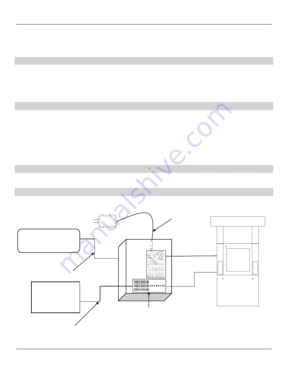
HARDWARE CONNECTIONS  


Data Distribution Box 

BENNETT 621 INTERCONNECTION BOX 

Dispenser 

Generic Current Loop 

(Up to 24 Fueling Points) 

AC Power Module 

Fuel Communication


Incoming 12 VDC


Fan-Out Board 

Interconnection Box 

RS485 Data


RS485 Data 

Summary of Contents for 104080

Page 1: ...ON BOX P N 115763 115VAC Fuel Positions 1 through 24 P N 104080 Fan Out Board Installation Service Manual 116186 Rev C 11 13 18 Only Trained Personnel May Work on This Equipment READ THIS MANUAL This...

Page 2: ...99 6202 Email sales bennettpump com or salesintl bennettpump com Website www bennettpump com For new manuals visit our web page at www bennettpump com IMPORTANT Examine the shipment immediately upon a...

Page 3: ...ions 3 Pump Controller Assembly 621 Box 4 SECTION 3 INSTALLATION INSTRUCTIONS 9 621 Interconnection Box Recommended Equipment and Materials 9 How To Mount the 621 Interconnection Box 9 AC Power Requir...

Page 4: ...Bennett 621 Interconnection Box Instruction Service Manual Table of Contents ii Page Intentionally Left Blank...

Page 5: ...authorized personnel only Warranty work may only be performed by Bennett certified technicians To prevent electric shock keep the electrical parts of the dispenser dry Electronic components are static...

Page 6: ...AUTHORIZED ALTERATION OF BENNETT PRODUCTS DANGER BEFORE PERFORMING ANY TYPE OF SERVICE TO THE DISPENSERS BE SURE TO SHUT OFF ALL ELECTRICAL SUPPLIES AND SECURE THEM IN THE OFF POSITION CLOSE ALL VALVE...

Page 7: ...id the Bennett technician to troubleshoot site occurrences The Fan Out Circuit Board provides additional terminal strips for RS485 Data Communication SPECIFICATIONS 621 Dimensions length x width x hei...

Page 8: ...el protocol 621 CIRCUIT BOARD ASSEMBLY For locations with 1 through 16 Fueling Points ITEM DESCRIPTION 1 Enclosure 2 Circuit Board Assembly 621 Generic Current Loop Adaptor 3 Circuit Board Assembly Fa...

Page 9: ...ser Each 621 Interconnection Box uses one 120V 50 60 Hz or 240V 50 60 Hz circuit for power Make sure the power source has the correct frequency and voltage JP1 CURRENT LOOP VOLTAGE The JP1 is a 3 pin...

Page 10: ...tive 23 24 Yellow negative 13 NOT USED Orange positive NOT USED Yellow negative 14 NOT USED Orange positive NOT USED Yellow negative 15 NOT USED Orange positive NOT USED Yellow negative 16 NOT USED Or...

Page 11: ...diagnostic purposes Note All switches must be in the ON position If one of the switches is in the OFF position the point of sale will not be able to communicate to the dispenser connected to that DATA...

Page 12: ...sition screw terminal strip provides a DATA negative connection for each debit credit terminal S1 S8 SWITCH Switches S1 S8 on the circuit board are used for diagnostic purposes Note All switches must...

Page 13: ...ction Box measures 12 x 12 x 4 The enclosure requires four mounting screws These four screws are on 10 by 10 centers Note When installing a 621 Interconnection Box pay attention to the locations of th...

Page 14: ...e and may void warranty Dispenser fuel communication wires for fueling positions 1 through 24 terminate directly to the 621 Circuit Board Each fueling point has a positive orange and negative yellow c...

Page 15: ...m occurs refer to the service and troubleshooting section for more information or call Bennett Technical Support at 1 800 423 6638 1 Apply power to dispensers program them for operation and address th...

Page 16: ...Bennett 621 Interconnection Box Instruction Service Manual Installation Instructions 12 CONNECTION DIAGRAM...

Page 17: ...T Red Generic Current Loop Transmit Fuel Controller D2 WR Red Generic Current Loop Receive Fuel Controller D3 BT Red Bennett Transmit Dispenser Communication D4 BR Red Bennett Receive Dispenser Commun...

Page 18: ...lender VRB Plus None or Select Grade 1 Diesel 4 High Grade 5 Blend 6 Low Grade Three Grade Mixer MGD Uni Hose None or Select Grade 1 Grade A 2 Grade B 3 Grade C One Grade Non Blender MGD Uni Hose None...

Page 19: ...lt equivalent All rebuilt boards have a part number prefix of RB You must use factory rebuilt parts for all warranty service work Please refer to the Distributor Policy Manual for program terms and de...

Page 20: ...Bennett 621 Interconnection Box Instruction Service Manual Parts 16 Page Intentionally Left Blank...

Page 21: ...Bennett 621 Interconnection Box Instruction Service Manual Bennett Limited Warranty...

Page 22: ...Bennett 1218 E Pontaluna Road Spring Lake MI 49456 USA 800 235 7618 Outside USA 231 798 1310 sales bennettpump com www bennettpump com...

Reviews: