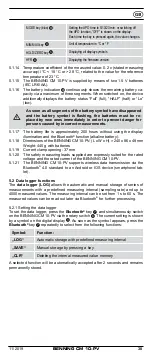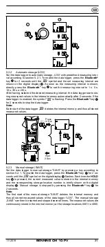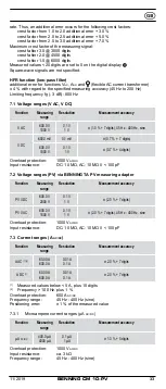
28
11/ 2019
BENNING CM 10–PV
4. Device description
See figure 1:
Device front
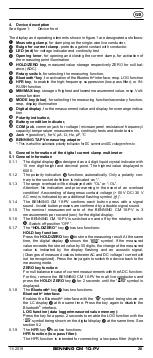
The display and operating elements shown in figure 1 are designated as follows:
1
Measuring clamp
, for clamping on the single-wire live conductor,
2
Bulge for current clamp
, protects against contact with conductor,
3
LED (red)
for voltage indicator and continuity test
4
Opening lever
, for opening and closing the current clamp, for activation of
the measuring point illumination
5
HOLD/ZERO key
, measured value storage respectively ZERO for null bal-
ance (ADC)
6
Rotary switch
, for selecting the measuring function,
7
Bluetooth
®
key
, for activation of the Bluetooth
®
interface, resp. LOG function
8
HFR key
, to enable the high-frequency suppression (low-pass filter), or IN-
RUSH function
9
MIN/MAX-key
, storage of highest and lowest measurement value, resp. Volt-
sense function
J
MODE key (blue)
, for selecting the measuring function/secondary function,
resp. display illumination
K
Digital display
, for the measurement value and display for overrange indica-
tion
L
Polarity indication,
M
Battery condition indicator,
N
COM jack
, common jack for voltage/ microampere/ resistance/ frequency/
capacity/ temperature measurements, continuity tests and diode tests
O
Jack +
(positive
1
), for V, µA, Ω, Hz, μF, °C
P
BENNING TA PV measuring adapter
1)
This is what the automatic polarity indication for DC current and DC voltage refers to
5. General information of the digital current clamp multimeter
5.1 General information
5.1.1 The digital display
K
is designed as a 4 digit liquid crystal indicator with
15 mm digit height and decimal point. The highest value displayed is
6000.
5.1.2 The polarity indication
L
functions automatically. Only a polarity con-
trary to the socket definition is indicated as “-“.
5.1.3 The range overload will be displayed with “OL” or “- OL”.
Attention: No indication and prior warning in the event of an overload
condition! A exceeding of dangerous contact voltage (> 60 V DC/ 30 V
AC rms) is indicated by an additional flashing symbol „(
)“.
5.1.4 The BENNING CM 10-PV confirms each button press with a signal
sound. Invalid button presses are confirmed by a double signal sound.
5.1.5 The nominal measurement rate of the BENNING CM 10-PV is 3
measurements per second (sec) for the digital display.
5.1.6 The BENNING CM 10-PV is switched on and off by the rotating switch
6
. Switch-off position “OFF”.
5.1.7 The
“HOLD/ZERO”
key
5
has two functions:
HOLD key function:
Press
the
HOLD/ZERO
key
5
to store the measuring result. At the same
time, the digital display
K
shows the “
HOLD
” symbol. If the measured
value exceeds the stored value by 50 digits, the change of the measured
value is indicated by the display flashing and an acoustic signal.
(Changes of measured values between AC and DC voltage / current will
not be recognized). Press the key again to switch the device back to the
measuring mode.
ZERO key function:
For null balance in case of current measurements with the A DC function.
For this, remove the BENNING CM 10-PV from all live conductors and
press the
HOLD/ ZERO
key
5
for 2 seconds until the “
ZERO
” symbol is
displayed.
5.1.8 The
Bluetooth
®
key
7
has two functions:
Bluetooth
®
interface:
Enables the Bluetooth
®
interface with the “ “ symbol being shown on
the LC display
K
at the same time. Press the key again to disable the
Bluetooth
®
interface.
LOG function (data logger/measured value memory):
Press the key for approx. 2 seconds to enable the LOG function with the
“
LOG
” symbol being shown on the digital display
K
at the same time. See
section 5.2
5.1.9 The
HFR
key
8
has two functions:
HFR function (low pass filter):
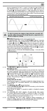
The HFR function is intended for connecting a low-pass filter (high-fre
-

