35
11/ 2019
BENNING CM 10–PV
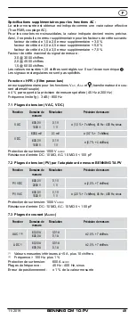
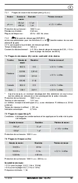
a change of the ambient temperature of ± 2 °C, the measuring accuracy data will
apply after 2 hour.
7.8 Measuring input of flexible AC current transformer ( )
Measuring range (1 mV/ 1 A)
Resolution
Measurement accuracy
[1]
300.0 A
0.1 A
± 1.5 % + 5 digits (45 Hz - 400 Hz)
3000 A
1 A
[1]
The measuring accuracy of the flexible current transformer BENNING CFlex 1
(item no. 044068) has not been taken into consideration.
Overload protection: 1000 V
AC/DC
8. Measuring with the BENNING CM 10-PV
8.1 Preparation for measuring
Store and use the BENNING CM 10-PV only under the correct temperature con-
ditions stated. Always avoid longer exposure to sunlight.
- Check the rated voltage and rated current stated on the safety measuring
leads. The safety measuring leads supplied with the unit are suitable for the
rated voltage and current of the BENNING CM 10-PV.
- Check the insulation of the safety measuring leads. If the insulation is dam-
aged in any way, do not use the leads.
- Check the continuity of the safety measuring leads. If the conductor in the
safety measuring lead is interrupted, do not use the leads.
- Before selecting another function with the rotating switch
6
, always discon-
nect the safety measuring leads from the measuring point.
- Sources of strong current in the vicinity of the BENNING CM 10-PV may
cause unstable or incorrect readings.
8.2 Voltage/ frequency measurement
Do not exceed the maximum permitted voltage with respect to
earth potential!
Please observe the overvoltage category of the electric circuit!
Attach the protective caps (CAT III/IV) to the contact tips be-
fore making measurements in circuits of overvoltage category
CAT III or IV.
Electrical danger!
The highest voltage that may be applied to the jacks
- COM jack
N
,
- jack +
O
of the BENNING CM 10-PV against ground is 600 V CAT IV/ 1000 V CAT III.
8.2.1 Voltage/ frequency measurement (switch position:
,
)
- Use the rotary switch
6
to select the required function
or
on
BENNING CM 10-PV.
- Connect the black safety measuring lead to the COM jack
N
of the BENNING
CM 10-PV.
- Connect the red safety measuring lead to the jack +
O
of the BENNING
CM 10-PV.
- Bring the safety measuring leads into contact with the measuring points
and read the measured value on the digital display
K
of the BENNING
CM 10-PV.
- In the
function, the
MODE
key (blue)
J
can be used for switching over
to frequency measurement (Hz).
- In the
function, the
MODE
key (blue)
J
can be used for switching over
to the mV range.
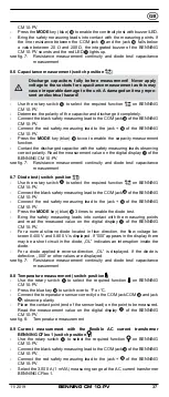
see fig. 2: Direct voltage measurement
see fig. 3: Alternating voltage measurement (frequency measurement)
8.2.2 Voltage measurement (switch position PV) using the BENNING TA PV
measuring adapter
For voltage measurements on PV systems with system voltages
of up to 1500 V DC, use the BENNING TA PV measuring adapter
and the switch position “PV” of the BENNING CM 10-PV only.
The measuring adapter reduces the voltage applied to the
BENNING CM 10-PV and is to be used exclusively for the
BENNING CM 10-PV! Electrical danger!

