10/ 2004
BENNING MM 4
14
- Contact the measurement points with the black safety test lead and the red
test probe. The measured value appears in the digital display
3
.
Note:
In low voltage ranges, the zero volts display does not appear due to interference
when the safety test leads are open. Check that the BENNING MM 4 is fully
functional by short-circuiting the test probe.
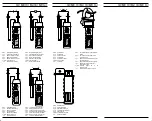
See fig. 2:
DC-voltage measurement
See fig. 3:
AC-voltage measurement
8.3 Resistance measurement
- With the slide switch
2
, the function button
4
and the RANGE button
6
of
the BENNING MM 4, select the desired range.
- Plug the black safety test lead into the COM socket
7
(black).
- Plug the red test probe into the V-Ω socket
8
(red).
- Contact the measurement points with the black safety test lead and the red
test probe. The measured value appears in the digital display
3
.
Important:
To obtain accurate measurements, ensure that no voltage is applied to the
measuring point.
With smaller resistances, the result can be improved by measuring the
resistance of the safety test lead beforehand by short-circuiting the test probe
and subtracting this resistance figure from the result.
See fig. 4:
Resistance measurement
8.4 Continuity test with buzzer
- With the slide switch
2
and the function button
4
select the range marked
with the buzzer symbol on the BENNING MM 4.
- Plug the black safety test lead into the COM socket
7
(black).
- Plug the red test probe into the V-Ω socket
8
(red).
- Contact the measurement points with the black safety test lead and the red
test probe. When the resistance between the measuring points drops below
50 Ω, the buzzer integrated in the BENNING MM 4 sounds.
See fig. 5:
Continuity test with buzzer
8.5 Diode testing
- With the slide switch
2
and the function button
4
select the range marked
with the diode symbol on the BENNING MM 4.
- Plug the black safety test lead into the COM socket
7
(black).
- Plug the red test probe into the V-Ω socket
8
(red).
- Contact the diode connections with the black safety test lead and the red test
probe. The value measured appears in the digital display
3
.
- For Si diodes located in conducting direction, the flow voltage of 0.500 V to
0.900 V is indicated. The reading “000” indicates a short circuit in the diode,
and the reading “OL” an interruption in the diode.
- For a diode located in the non-conducting direction “OL” appears. If the
diode is defective, “000” or other figures appear.
See fig. 6:
Diode testing
8.6 AC current measurement with the current transducer
8.6.1 Preparation for measurement
Use and store the current transducer only at the specified temperature
conditions for storage and working. Avoid prolonged exposure to sunlight.
- Strong sources of interference in the vicinity of the BENNING MM 4 may
cause unstable indications and measurement errors.
Do not apply voltage to the output contacts of the current
transducer. The current transducer should be applied to a live
conductor only when it is connected with the Multimeter.
Max. current of enclosed current transducer 300 A!
8.6.2 Current measurement
- Contact the current transducer firmly with the Multimeter.
- Switch on the voltage measurement on the Multimeter. Press the blue
button 2 s and select the desired range with the RANGE button. (Amp
CLAMP)
- Press the opening lever
9
. With the current transducer, grip the single-wire
conductor with the current to be measured.
- The reading appears in the digital display
3
.
See fig. 7:
AC current measurement with current transducer
9. Maintenance

