03/ 2011
BENNING MM 11
27
the BENNING MM 11 (press key once)
- The black safety measuring lead has to be connected to the COM jack
on the BENNING MM 11.
- The red safety measuring lead has to be connected to the jack for V,
Ω
, Hz,
°C,
on the BENNING MM 11.
- The safety measuring leads have to be brought into contact with the meas-
uring points. If the line resistance between the COM jack
and the jack for
V,
Ω
, Hz, °C,
50
Ω
, the fitted buzzer sounds on the BENNING MM 11.
See figure 8:
Continuity testing with buzzer
8.6 Capacity measurement
Before carrying out capacity measurements discharge
capacitors completely!
Never apply voltage to the capacity measurement jacks! The
appliance can become damaged or even be destroyed! A
damaged appliance may cause an electrical hazard!
- Use the rotary switch
to select the required function (
) on the
BENNING MM 11.
- Determine the polarity of the capacitor and discharge capacitor complete-
ly.
- The black safety measuring lead has to be connected to the COM jack
on the BENNING MM 11.
- The red safety measuring lead has to be connected to the jack for V,
Ω
, Hz,
°C,
on the BENNING MM 11.
- The safety measuring leads have to be brought into contact with the dis-
charged capacitor according to its polarity, read the measured value on the
digital display
unit of the BENNING MM 11.
See figure 9:
Capacity measurements
8.7 Frequency measurement
- Using the rotary switch
select the required function (Hz, %DF) on the
BENNING MM 11.
- The black safety measuring lead has to be connected to the COM jack
on the BENNING MM 11.
- The red safety measuring lead has to be connected to the jack for V,
Ω
, Hz,
°C,
on the BENNING MM 11. Note the minimum sensitivity for the
frequency measurements on the BENNING MM 11!
-
Bring the safety measuring leads into contact with the measuring points, read
the measured value on the digital display
unit of the BENNING MM 11.
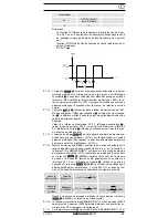
See figure 10:
Frequency-/ pulse duty ratio measurement
8.8 Pulse duty ratio measurement
- Using the rotary switch
select the required function (Hz, %DF) on the
BENNING MM 11.
- Using the button (blue)
carry out the switchover to pulse duty ratio meas-
urement (%DF) on the BENNING MM 11 (press key once)
- The black safety measuring lead has to be connected to the COM jack
on the BENNING MM 11.
- The red safety measuring lead has to be connected to the jack for V,
Ω
, Hz,
°C,
on the BENNING MM 11. Note the minimum sensitivity for the
frequency measurements on the BENNING MM 11!
-
Bring the safety measuring leads into contact with the measuring points, read
the measured value on the digital display
unit of the BENNING MM 11.
See figure 10:
Frequency-/ pulse duty ratio measurement
8.9 Temperature measurement
- Use the rotary switch
to select the required function (°C or °F) on the
BENNING MM 11.
- Bring the adapter for the temperature sensor in the COM jack
and V,
,
Hz, °C,
into pole-correct contact.
- The temperature sensor (type K) must be contacted in the adapter.
- The contact point (end of the sensor line) has to be placed at the point to
be measured. Read the measured value on the digital display
unit of the
BENNING MM 11.
See figure 11:
Temperature measurement
9. Maintenance
Before opening the BENNING MM 11, make sure that it is free of
voltage! Electrical danger!
Work on the opened BENNING MM 11 under voltage may be carried out
only

