background image

07/ 2016 

  BENNING  MM  12


24

 

As soon as all segments of the battery symbol have disappeared and 

the battery symbol is flashing, the batteries must be replaced by new 

ones immediately in order to prevent danger for persons due to incorrect 

measurements.

5.1.12 

The life span of a battery is approx. 50 hours (alkali battery).

5.1.13 

Appliance dimensions:


(L x W x H) = 200 x 87 x 40 mm without protective rubber holster


(L x W x H) = 206 x 94 x 54 mm with protective rubber holster


Appliance weight:


480 g without protective rubber holster


640 g with protective rubber holster

5.1.14 

The safety measuring leads supplied are expressly suited for the rated voltage and the 

rated current of the BENNING MM 12.

5.1.15 

The BENNING MM 12 is protected against mechanical damage by a protective rub-

ber holster 

O

. The protective rubber holster 

O

 makes it possible to suspend the 

BENNING MM 12 during the measuring process or to stand it upright.

5.1.16 

The BENNING MM 12 has an optical interface 

P

 on the top side. This is used for the 

galvanic isolation of the measuring signal to a PC/ laptop. The enclosed data cable is 

used for the transmission of measuring data and is equipped with a USB 2.0 compa-

tible connection.

5.1.17 

The BENNING MM 12 supports wireless data transmission via the Bluetooth

®

 4.0 

standard to an Android or IOS device (smartphone/tablet). 

5.2  Key functions

The operating keys 

5

6

8

 and 

9

 are provided with a double function and can be pressed 

upwards/ ▲ and downwards/ ▼.

5.2.1  

The 

RANGE

 key 

5

 (up/ ▲) can be used to change over to the manual measuring 

ranges and to hide “AUTO” on the display at the same time. Press the key for approx. 

2 seconds to activate the automatic range selection (“AUTO” on the display).

5.2.2  

Press the 

Function

 key 

5

 (down/ ▼) to select the secondary, third or fourth function 

of the rotary switch position:

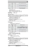
Rotary switch position:

Secondary function:

Third / fourth function:

V AC

Hz

mV AC

Hz

V DC

V AC + DC

mV DC

mV AC + DC


A AC

A DC

A AC + DC/ Hz

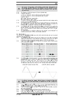
5.2.3  

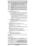
The 

HFR

 key 

6

 (up/ ▲) is intended for connecting a 

low-pass filter (high-frequency 

suppression)

 in the V AC and A AC functions in order to filter out high-frequency 

pulses e. g. at pulsed motor drives. “HRF” symbol on the LC display 

1

. The limiting 

frequency (- 3 dB) of the filter is fg = 800 Hz. When reaching the limiting frequency fg, 

the displayed value is lower by a factor of 0.707 than the actual value without filter. 

without HRF (without low-pass filter)

with HRF (with low-pass filter)

In order to prevent any danger, always measure a present voltage first 

without low-pass filter (high-frequency suppression) to detect a dangerous 

voltage.

5.2.4  

Press the   

Bluetooth

®

 key 

6

 (down/ ▼) to activate the 

Bluetooth® interface

 with 

the    symbol shown on the LC display 

1

 at the same time.

5.2.5  

Press the 

Cursor

 key 

7

 (up/ ▲, down/ ▼, right/ ►, left/ ◄) to select the menu func

-

tion on the LC display 

1

.

5.2.6  

Press the 

ENTER

 key 

8

 (up/ ▲) to confirm the selected function.

5.2.7  

Press the 

CANCEL

 key 

8

 down/ ▼) to terminate a selected function.

5.2.8  

Press the 

A-HOLD

 key 

9

 (up/ ▲) (automatic storage of measured values) to store 

the displayed values on the secondary display 

2

. The “Auto HOLD” symbol simulta

-

Summary of Contents for MM 1-2

Page 1: ...F C mVAF Mk Hz MM 12 600V CAT IV 1000V CAT III AutoV LoZ RANGE HFR ENTER A HOLD CANCEL P HOLD C F AC DC AC DC AC DC MAX 400 mA FUSED MAX 10 A FUSED mA COM Hz V A mV D Bedienungsanleitung Operating ma...

Page 2: ...eak HOLD AUTOTEST T POINT AC DC s F C mVAF Mk Hz MM 12 600V CAT IV 1000V CAT III AutoV LoZ RANGE HFR ENTER A HOLD CANCEL P HOLD C F AC DC AC DC AC DC MAX 400 mA FUSED MAX 10 A FUSED mA COM Hz V A mV 0...

Page 3: ...VE LOAD CLR RATE LOG MEM MAX MIN AVG dBm HFR ms VAFs MkHz AutoPeak HOLD AUTOTEST T POINT AC DC s F C mVAF Mk Hz MM 12 600V CAT IV 1000V CAT III AutoV LoZ RANGE HFR ENTER A HOLD CANCEL P HOLD C F AC DC...

Page 4: ...TUP A SAVE SAVE LOAD CLR RATE LOG MEM MAX MIN AVG dBm HFR ms VAFs MkHz AutoPeak HOLD AUTOTEST T POINT AC DC s F C mVAF Mk Hz MM 12 600V CAT IV 1000V CAT III AutoV LoZ RANGE HFR ENTER A HOLD CANCEL P H...

Page 5: ...SETUP A SAVE SAVE LOAD CLR RATE LOG MEM MAX MIN AVG dBm HFR ms VAFs MkHz AutoPeak HOLD AUTOTEST T POINT AC DC s F C mVAF Mk Hz MM 12 600V CAT IV 1000V CAT III AutoV LoZ RANGE HFR ENTER A HOLD CANCEL...

Page 6: ...07 2016 BENNING MM 12 6 D Bild 14 Aufwicklung der Sicherheitsmessleitung Fig 14 Winding up the safety measuring leads Bild 15 Aufstellung des BENNING MM 12 Fig 15 Standing up the BENNING MM 12...

Page 7: ...kreisen mit einer h heren Nennspannung als 1000 V AC DC eingesetzt werden N heres hierzu im Abschnitt 6 Umgebungsbedingungen In der Bedienungsanleitung und auf dem BENNING MM 12 werden folgende Symbol...

Page 8: ...rdung auszuschlie en messen Sie eine vorhandene Spannung zuerst immer ohne Tiefpassfilter ohne Hochfrequenzunterdr ckung um eine gef hrliche Spannung zu erkennen Vor jeder Inbetriebnahme berpr fen Sie...

Page 9: ...me bis 400 mA N Buchse positive1 f r 10 A Bereich f r Str me bis 10 A O Gummi Schutzrahmen P optische Schnittstelle zur Aufnahme des am Datenkabels befindlichen Adapters Q Lichtsensor f r Beleuchtung...

Page 10: ...tenkabel dient der Messdaten bertragung und ist mit einem USB 2 0 kompatiblen Anschluss ausger stet 5 1 17 Das BENNING MM 12 unterst tzt die drahtlose Daten bertragung per Bluetooth 4 0 Standard zu ei...

Page 11: ...peichert automatisch den h chsten Messwert MAX den niedrigsten Messwert MIN und den Mittelwert AVG einer Messreihe und zeigt den jeweiligen Wert im Unterdisplay 2 an Durch Bet tigung der Taste CANCEL...

Page 12: ...rsor 7 k nnen Sie folgende Untermen s anw hlen SAVE Die Taste ENTER 8 oben startet die Datenlogger Funktion LOG Bei erneuter Bet tigung der Taste ENTER 8 oben pausiert die Messung nach nochmaliger Bet...

Page 13: ...n Grafische Darstellung der vom Multimeter erfassten Messwerte in Echtzeit und Speicherung als MS Excel Datei Die maximale Anzahl der Messwerte ist auf 100 000 Messwerte beschr nkt Die Abtastrate ist...

Page 14: ...ehler von 1 ber cksichtigt werden Bei nichtsinusf rmigen Kurvenformen wird der Anzeigewert ungenauer So ergibt sich f r folgende Crest Faktoren ein zus tzlicher Fehler Crest Factor von 1 4 bis 2 0 zus...

Page 15: ...Leerlaufspannung ca 2 5 V Max Kurzschlussstrom ca 0 1 mA 7 4 Diodenpr fung berlastschutz 1000 VAC DC Messbereich Aufl sung Messgenauigkeit 2 000 V 1 mV 1 5 des Messwertes 3 Digit Max Leerlaufspannung...

Page 16: ...Nennstrom dem BENNING MM 12 Isolation der Sicherheitsmessleitungen berpr fen Wenn die Isolation besch digt ist sind die Sicherheitsmessleitungen sofort auszusondern Sicherheitsmessleitungen auf Durch...

Page 17: ...eigt Die Anzeige OL deutet auf einen Kurzschluss oder eine Unterbrechung in der Diode hin F r eine in Sperrrichtung angelegte Diode wird eine negative Flussspannung zwischen 0 400 V bis 0 900 V angeze...

Page 18: ...en von au erordentlicher Transportbeanspruchung In diesen F llen ist das BENNING MM 12 sofort abzuschalten von den Messstellen zu entfernen und gegen erneute Nutzung zu sichern 9 2 Reinigung Reinigen...

Page 19: ...ce Center Robert Bosch Str 20 D 46397 Bocholt 9 6 Ersatzteile Sicherung F 440 mA 1000 V 10 kA D 10 mm L 34 9 mm T Nr 10016655 Sicherung F 11 A 1000 V 20 kA D 10 3 mm L 38 1 mm T Nr 10016656 10 Anwendu...

Page 20: ...07 2016 BENNING MM 12 20 D 12 Umweltschutz Bitte f hren Sie das Ger t am Ende seiner Lebensdauer den zur Verf gung ste hen den R ckgabe und Sammelsystemen zu...

Page 21: ...ed for measurements in dry surroundings It must not be used in electrical circuits with rated voltages higher than 1000 V AC DC For more details see in section 6 Ambient conditions The following symbo...

Page 22: ...erous voltage Before starting the multimeter always check it as well as all measuring leads and wires for signs of damage Should it appear that safe operation of the multimeter is no longer possible i...

Page 23: ...Multimeter functions 5 1 General data 5 1 1 The digital display 1 is designed as a 3 or 4 digit liquid crystal indicator with 15 mm digit height and decimal point The highest value displayed is 4 000...

Page 24: ...ds and downwards 5 2 1 The RANGE key 5 up can be used to change over to the manual measuring ranges and to hide AUTO on the display at the same time Press the key for approx 2 seconds to activate the...

Page 25: ...lue function stores the currently displayed value on the secondary display 2 and shows the difference offset between the stored measured value and the following measured values on the display 1 Exampl...

Page 26: ...up to delete all measured values stored in the data logger LOG RATE Press the ENTER key 8 up to set the sampling rate defining the time interval between two measuring points Use the Cursor key 7 to a...

Page 27: ...me wireless transmission of measured values to an Android or IOS device The BENNING MM CM Link app required for this is available in the Google Play Store and in the Apple App Store 6 Ambient conditio...

Page 28: ...ges Overload protection 440 mA 1000 V fuse 10 kA rapid on mA input 11 A 1000 V fuse 20 kA rapid on A input Function Measuring range Resolution Measurement accuracy AC 40 00 mA 0 01 mA Sine curve 0 8 o...

Page 29: ...buzzer sounds at a resistance R lower than 30 preset The resistance value can be set within a range from 10 to 50 7 6 Capacity ranges Overload protection 1000 VAC DC Conditions Capacitors discharged...

Page 30: ...ings 8 2 Voltage and current measurement Always observe the maximum voltage to earth potential Electrical hazard The maximum voltage which may be applied to the sockets COM socket L socket for V Hz K...

Page 31: ...NING MM 12 sounds See figure 8 Continuity testing with buzzer 8 6 Capacity measurement Discharge capacitors fully before measurement Never apply voltage to the sockets for capacitance measurement as t...

Page 32: ...eared and the battery symbol is flashing Proceed as follows to replace the batteries First remove the safety measuring leads from the measurement circuit Remove the safety measuring leads from the BEN...

Page 33: ...ng the measuring probe and the BENNING MM 12 up to the measuring point together The support at the back of the holster O can be used to prop the BENNING MM 12 up in a diagonal position to make reading...

Page 34: ...Benning Elektrotechnik Elektronik GmbH Co KG M nsterstra e 135 137 D 46397 Bocholt Phone 49 0 2871 93 0 Fax 49 0 2871 93 429 www benning de E Mail duspol benning de...

Reviews: