background image

55 


4.


Disassembly finished. 


(5) 

Summary of Contents for Aries Lite

Page 1: ...e 2008 08 15 Notice For RO to input specific Legal Requirement in specific NS regarding to responsibility and liability statements Please check BenQ s eSupport web site http esupport benq com to ensure that you have the most recent version of this manual First Edition Aug 2008 Copyright BenQ Corporation 2008 All Right Reserved ...

Page 2: ...ent 4 General Descriptions 5 Service Web Site 5 Product Overview 6 Specifications 6 HW Spec 6 SW Spec 8 Product Views 11 L1 L2 Repair Definition 13 System Update and Restore 14 Tools required 14 BIOS and EC Update 15 OS Restore 23 Cap Sensor Driver Update 23 Disassembly and Assembly 36 Exploded View 36 Layout 39 Disassembly Procedure 45 Rear Case and Main PCB Disassembly 45 Front Case Disassembly ...

Page 3: ...o Service HSDPA High Speed Download Packet Access HSUPA High Speed Uplink Packet Access LCD LCDM Liquid Crystal Display Module MB Main board or Mother board MMI Machine Man Interface MMS Multimedia Messaging Service PCB Printed circuit board RF Radio frequency SD Secure digital SMS Short Message Service S W Software TFT Thin Film Transistors UMTS Universal Mobile Telecommunications System USIM Uni...

Page 4: ...tion contains general service information please read through carefully It should be stored for easy access place Important Service Information RoHS 2002 95 EC Requirements Applied to all countries require RoHS The RoHS Restriction of Hazardous Substance in Electrical and Electronic Equipment Directive is a legal requirement by EU European Union for the global electronics industry which sold in EU...

Page 5: ...ing electrical components are sensitive to electrostatic discharge ESD Follow ESD safety procedures while handling these parts 8 Some products contain more than one battery Do not disassemble any battery or expose it to high temperatures such as throwing into fire or it may explode 9 Refer to government requirements for battery recycling or disposal Compliance Statement 1 Caution This Optical Stor...

Page 6: ...400 533 MHz FSB DDR II 400 533 MHz Full Hardware decode acceleration for MPEG4 H 264 and WMV9 VC1 USB One mini USB2 0 port host client Audio HD audio codec Speaker One for audio output Microphone Integrated microphone supported Main Memory 1 On board SDRAM design 2 512MB DDR2 533MHz SDRAM HDD 1 PATA interface 2 SSD solid state disk capacity 2GB End user memory 256M Memory Card Reader Micro SD SDHC...

Page 7: ...enna Internal type for all antennas Wi Fi antenna depends on the need Webcam N A G sensor 3 axiel G sensor Buttons Solid system function control buttons 1 Power button 2 G sensor button 3 Cap sensor button 4 Home button 5 Software keypad launch button LED indicator 1 WWAN blue color 2 Charging Amber 3 System blue color Battery 7 4V 1880mAh with 2 cell Li ion battery AC Adapter BenQ Universal 3 pin...

Page 8: ...chment Yes E mail capacity Share SSD storages Audio Integrated Handsfree speaker Speaker Phone Yes Music Player RealPlayer Audio decode 8 16 bit pcm Window Media Audio RealAudio MP3 Vorbis Audio format wav au aiff aac wma rm mp3 ogg Music background play Yes Video Video Player RealPlayer Video decode RealVideo Windows Media Video 9 VC 1 Theora H 263 H 263 H 264 MPEG4 Video format rm wmv asf ogm mp...

Page 9: ...s Full screen mode Yes HTTPS Yes Flash Plug ins Yes Java Plug ins Yes PDF Plug ins Yes Multi media Plug ins Yes Auto complete Yes Auto show history Yes Bluetooth Advanced Audio Distribution Profile A2DP Yes Human Interface Device HID Yes USB USB 2 0 high speed Yes Languages Input OS Languages Italian English Qwerty input method Yes Software keypad Touch screen Yes ...

Page 10: ... Mah Jong Yes File Manager Yes SIM Manager Yes contact copy E book Yes PDF Reader Yes Calendar Yes RSS Reader Yes Install Yes Backup Yes USB Client Yes BT Utility Yes Connection Manager Yes3 Touch Screen Calibration Yes System Updater Yes4 Notes 1 Redflag is the company providing software platform of Linux 2 Redoffice is the company providing office software customized from open office 3 WiFi and ...

Page 11: ...en 2 Touch Zone Cap sensor 3 Home Button 4 Keypad Button 5 Power Button 6 Ventilation Holes 7 Headset Jack 8 microSD Slot 9 Motion Sensor Button 10 System Indicator 11 WLAN Indicator 12 WWAN Indicator 13 Power Indicator 14 Speaker ...

Page 12: ...12 1 Stylus Device for tapping the touch screen 2 USB Socket 3 Power Socket 1 Stylus 2 Ventilation Holes 3 Foot Stand 4 Battery Cover ...

Page 13: ...rnal Antenna DOA swap Service Tool L1 GRT SW GRT equipment Download cables PC or Notebook Level 2 Cosmetic repairs exchange of non soldered parts Housing Lens Keypad Side key Metal dome Flex cable FPC LCD holder Speaker Receiver Laud speaker Laud speaker cap Microphone Vibrator DSC module LCD module Sub LCD module OLED module Service Tool L1 GRT SW GRT equipment Download cables PC or Notebook T5 s...

Page 14: ... Update and Restore 1 Tools required 1 1 USB disk stick recommend to prepare 2 sticks 1 for BIOS update 1 for OS restore BenQ suggests the best capacity of USB disk for OS restore is 4GB 1 2 USB extension cable ...

Page 15: ...15 1 3USB hub 1 4 USB keyboard 2 BIOS and EC update 2 1 Install SP27213 EXE HP tool 2 1 1 Double click on the icon of SP27213 ...

Page 16: ...16 2 1 2 Click on Next 2 1 3 Choose to accept the agreement and click Next ...

Page 17: ...17 2 1 4 Installing 2 1 5 Install complete ...

Page 18: ...DOS USB memory Stick to PC 2 3 Plug in USB memory stick 2 4 Execute HP USB Disk Storage Format Tool 2 5 Tool setting 2 5 1 Click Create a DOS setup disk 2 5 2 Direct the Using DOS system files located at to the path of STEP2 2 5 3 Click Start ...

Page 19: ...19 2 5 4 Warning message showed and make sure you did not store anything important in the USB disk before click Yes ...

Page 20: ...20 2 5 5 Formatting USB disk 2 5 6 USB disk formatted and click Yes ...

Page 21: ... Copy the folder which BIOS and tool is stored into USB disk stick The folder should contend 3 files as listed below A batch file a BIOS ROM and AFUDOS 2 7 Connect USB disk stick and USB keyboard onto the USB hub and connect the whole set to MID ...

Page 22: ...22 2 8 Turn on MID and it will boot from USB disk stick 2 9 On DOS screen type in cd folder name to enter the folder In this case 0811bios is the folder name ...

Page 23: ...ice is connected to AC power before performing the operation Before you perform the system recovery make sure that you have the following items on hand z the recovery DVD that came with your device z a computer that comes with a optical drive which can read DVD format z a completely empty USB flash drive with minimum capacity of 2 GB z the provided USB connection cable 3 1 1 Recovering the device ...

Page 24: ...pears You need to select the USB flash drive to create Recovery USB Disk Select the USB flash drive carefully if you have more than one USB flash drive connected to your computer at the same time All the data on the one used for system recovery will be erased ...

Page 25: ...xit Step5 Please insert the USB Disk into your MID and boot your MID to complete the process The software version on the provided Recovery DVD may not be the latest one After you have restored your device to the factory default settings all the programs you installed after purchase have been removed It is recommended that you visit the BenQ server for software ...

Page 26: ...isk on Windows XP Vista environment 3 2 1 Install WinImage 3 2 1 1 Double click the icon to install 3 2 1 2 Click Next 3 2 1 3 Enter Name and Registration Code Please be noted this user name and code could be expired WinImage official website advices that unregistered version can use for 30 days trial Please visit WinImage official website http www winimage com for ...

Page 27: ...27 registration information 3 2 1 4 Keep to click Next until installation complete and click Finish 3 2 2 Copy Syslinux directory to your XP environment e g c ...

Page 28: ...28 3 2 3 Format your USB disk e g g with the FAT32 file system 3 2 4 Launch WinImage and choose USB Disk ...

Page 29: ...29 3 2 5 Open the image you download 3 2 6 Extract to your USB disk ps use the Extract with pathname option ...

Page 30: ...30 3 2 7 Close WinImage 3 2 8 Launch command line console and type the following commands cd syslinux syslinux fma g ...

Page 31: ...download with USB disk stick Step 1 Prepare the bootable USB flash drive Step 2 Insert the bootable USB flash drive into the MID Step 3 Power on the MID Step 4 Press HOME Key to select the booting up from USB device ...

Page 32: ...32 Step 5 Press Motion Sensor Button to confirm the download process If you press a key other than Motion Sensor Button it will not download the OS ...

Page 33: ...33 Step 6 After pressing the Motion Sensor Button auto download starts Step 7 After downloading the OS please remove the bootable USB flash drive and reboot ...

Page 34: ...34 Step 8 Power ON and enter OS Check the OS version Please clicking View within setting menu Then you can check the OS version within System Information ...

Page 35: ...USB disk stick with DOS Can be the same one as BIOS update Step2 Copy the new BIN file to CAP folder in USB disk stick by PC Step3 Plug in the USB stick to MID and then boot the device Step4 Cmd C cd CAP Step5 Cmd XX bin file name e g update 26 bin ...

Page 36: ...36 Disassembly Assembly Exploded view ...

Page 37: ... Cond LCDM MID AriB1A 1 13 4K Y2909 001 Mesh Wire Antenna AriB1A 1 14 4G Y2917 001 Cushion Cond SHD Ram AriB1A 1 15 4G Y2923 001 Cushion Support LCDM MID AriB1A 1 16 4K Y2915 001 Film Mesh Conn LCDM MID AriB1A 1 17 6K Y2908 001 Assy SHD EC MID AriB1A 1 18 3D Y2914 001 SHD Cover RAM SUS304 MID AriB1A 1 19 5K Y2901 001 Cable LCDM AriB1A 1 20 5D Y2901 M01 PCBA Main BD AriB1A SMD 1 21 6E Y2903 001 Ass...

Page 38: ...lack AriB1A 1 35 4K Y2911 001 Mylar Wire Fan MID AriB1A 1 36 6K Y2906 001 Assy Case Rear AriB1A Lite 1 37 4B Y2910 001 Stylus POM AriB1A 2 38 4G Y2914 001 Rubber Screw C AriB1A Lite 1 39 4G Y2909 001 Rubber Screw A AriB1A 1 40 8F 20145 001 Screw FPH M2 0 4 14 5L BZn Ny 1 41 8F 206R0 001 Screw FPH M2 6 0L BZn Nylok 3 42 2C 20Y29 001 Batt Li 7 4V 1900mah AriB1A 1 43 6K Y2907 001 Assy Cover Battery A...

Page 39: ...39 Layout Components back side Front panel ...

Page 40: ...40 Mainboard back side Main board front side ...

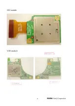
Page 41: ...41 SSD module WiFi module ...

Page 42: ... 16 SSD IDE Power On Power Plan 25 26 27 PMIC HDA USB5 RX TX 23 AUDIO I F 19 8513 1 5V FUJIYAMA IC 3V 5V 1 8V 0 9V USB Client Page GPIOSUS3 Power P 26 P 26 P 27 P 27 1 05V Vcore MAX8796 P 28 Bus 7A 7B Menlow Form Factor 0806 For PPR Battery H8 I2C Bus 1 Poulsbo I2C Bus Touch Button G Sensor H8 I2C Bus 2 0 3M CAM On Board RX TX FUJIYAMA FUJIYAMA FUJIYAMA Level Shifter 22 29 G Sensor HOST 28 C6 Swit...

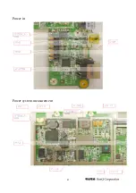
Page 43: ...43 Power in Power system measurement ...

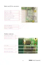
Page 44: ...44 Battery and DC in connectors Headset connector ...

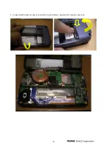
Page 45: ...ure for removing and accessing various parts of the phone Rear Case and Main PCB Disassembly 1 Turn off power and remove attachments shown in following figure 1 Screw cap 2 2 battery cover 3 battery 4 stylus 2 Screw off four screws between rear case and front case 1 2 3 4 ...

Page 46: ...46 3 Loosen side hooks on case rear and fix top of battery connector to remove case rear ...

Page 47: ...47 4 Disconnect sensor FPC from main PCB and LCDM cable from LCDM 5 Disconnect 1 FPC of G key PCB 2 SPK wire and tear off 3 mesh and remove 4 LCDM cable from PCB then main PCB will be unloaded 1 2 3 4 ...

Page 48: ...ate antenna from main board 1 Disconnect 3G wire from H10 2 disconnect BT wire from WLAN PCB 3 tear off Mylar for fixed wire and 4 screw off 2 screws to remove antenna 7 Take RTC battery out from main PCB 1 4 2 3 ...

Page 49: ...rom main board 1 unscrew 1 2 tear off supportable Mylar from WLAN PCB 9 Remove SSD PCB and FPC 1 Tear off Mylar for fixing fan wire 2 screw off 2 3 disconnect SSD FPC from main PCB and 4 remove SSD FPC from SSD PCB 1 3 4 2 1 2 ...

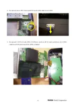
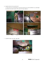
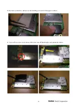
Page 50: ...50 10 Remove conductive cushion on the shielding case and LCM support cushion 11 Screw off one screws and remove H10 then tear off black Mylar and conductive fabric ...

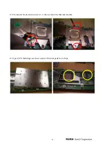
Page 51: ...51 12 Disconnect the fan and unscrew 2 then remove the thermal module 13 Open CPU shielding case then remove 2 thermal pads from chips ...

Page 52: ...52 14 Main PCB finished Front Case Disassembly ...

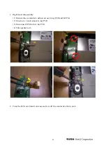
Page 53: ...ly 1 Remove the conductive cushion across G key PCB and LCDM 2 Unscrew 2 and remove G key PCB 3 Disconnect FPC from G key PCB 4 Take speaker out 2 Take the LCM out from front case and tear off the conductive fabric on it 1 2 3 4 ...

Page 54: ...ezel disassembly 1 Disconnect MIC wire from sensor FPC 2 Unscrew 2 and loose the hooks to remove bezel 3 Take microphone out 4 Use tweezers to remove sensor PCB from bezel 5 Remove home key 1 2 3 4 Hooks location ...

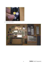
Page 55: ...55 4 Disassembly finished 5 ...

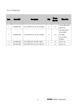
Page 56: ...4 001 Screw FPH M2 0 4 2 4L Ni Nylok 4 1 4 Thermal Module SSD PCB 2 8F 203R5 001 Screw FPH M2 0 4 3 5L Ni Nylok 8 1 6 Assy Bezel Left G Key PCB Antenna WLAN PCB HSDPA 3 8F 206R0 001 Screw FPH M2 6 0L BZn Nylok 3 1 6 Rear Case 4 8F 20145 001 Screw FPH M2 0 4 14 5L BZn Ny 1 1 6 Rear Case ...

Reviews: