background image

15

GAMMA SELECTION

Gamma is what controls the overall brightness of an image. 

Images which are not corrected  properly can appear too white 

or too dark, so controlling the gamma properly can have a huge 

influence on the overall picture quality of your display.

The options are: {

NATIVE

} / {

2.2

} / {

2.4

} / {

S GAMMA

}.

NOISE REDUCTION

Adjust to remove the noise in the image. You can select a 

suitable noise reduction level.
The options are: {

OFF

} / {

LOW

} / {

MIDDLE

} / {

HIGH

}.

NOTE:   This item is functional for 

HDMI

(Video mode), 

Video

and 

YPbPr

 inputs only.

FILM MODE

Choose to turn on or off the film mode frame conversion 

function.

• 

{

AUTO

} - Enable the film mode frame conversion function 

for movies and motion pictures. The display converts a 

24 frames-per-second (24 fps) input signal format to DVD 

video signal format. Once this function is enabled, it is 

recommended that you set the {

SCAN CONVERSION

function to {

PROGRESSIVE

}.

• 

{

OFF

} - Disable the film mode frame conversion function. 

This mode is suitable for TV broadcasting and VCR signals.

PICTURE RESET

Reset all settings in the Picture menu to factory preset values.

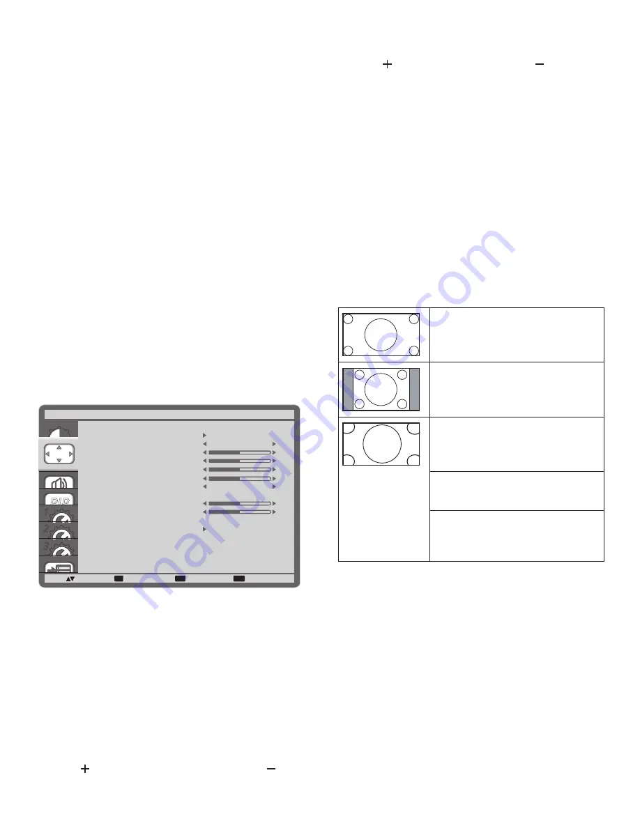
4.2.2.  SCREEN menu

PIP

1
2
3

SET

EXIT

MENU

:SEL

:NEXT

AUTO SETUP

AUTO ADJUST

H POSITION

V POSITION

CLOCK

CLOCK PHASE

ZOOM MODE

CUSTOM ZOOM

H RESOLUTION

V RESOLUTION

INPUT RESOLUTION

SCREEN RESET

SCREEN

:RETURN

:EXIT MENU

50

50

2200

66

1920

1080

FULL

OFF

AUTO SETUP

Use this function to let the display automatically optimize the 

display of VGA input image.
NOTE:   This item is functional for 

VGA

 input only.

AUTO ADJUST

Choose to let the display detect and display available signal 

sources automatically.

• 

{

ON

} - Set the display to display the image automatically 

once a signal is connected.

• 

{

OFF

} - Once a signal is connected, it can only be selected 

manually.

H POSITION

Press the [ ] button to move the image to the right, or [ ] to 

move the image to the left.

V POSITION

Press the [ ] button to move the image up, or [ ] to move the 

image down.

CLOCK

Adjust the width of the image.
NOTE:   This item is functional for 

VGA

 input only.

CLOCK PHASE

Adjust to improve the focus, clarity and stability of the image.
NOTE:   This item is functional for 

VGA

 input only.

ZOOM MODE

The pictures you receive may be transmitted in 16:9 format 

(wide screen) or 4:3 format (conventional screen). The 16:9 

pictures sometimes have a black band at the top and bottom of 

the screen (letterbox format).
This function allows you to optimize the picture display on 

screen. The following zoom modes are available for: 

• 

PC mode: {

FULL

} / {

NORMAL

} / {

CUSTOM

} / {

REAL

}.

• 

Video mode: {

FULL

} / {

NORMAL

} / {

DYNAMIC

} / 

{

CUSTOM

} / {

REAL

}.

FULL 

This mode restores the correct 

proportions of pictures transmitted in 

16:9 using the full screen display. 

NORMAL 

The picture is reproduced in 4:3 format 

and a black band is displayed on either 

side of the picture.

DYNAMIC 

Fill the entire screen by stretching 4:3 

pictures non-proportionally.

CUSTOM 

Choose to apply the custom zoom 

settings in the Custom Zoom submenu.

REAL 

This mode displays the image pixel-

by-pixel on screen without scaling the 

original image size.

Summary of Contents for SL461A

Page 1: ...SL461A Digital Signage User Manual ...

Page 2: ... 1 1 4 Installing and Removing Table Stands optional 2 1 5 Installing and Removing OPS module SL461A optional 3 1 6 Mounting on a Wall 4 1 6 1 VESA Grid 4 2 Parts and Functions 5 2 1 Control Panel 5 2 2 Input Output Terminals 6 2 3 Remote Control 7 2 3 1 General functions 7 2 3 2 Inserting the batteries in the remote control 8 2 3 3 Handling the remote control 8 2 3 4 Operating range of the remote...

Page 3: ... cover and screw M3x8 x1 NOTES An approved power cord greater or equal to H05VV F 3G 0 75mm2 must be used For all other regions apply a power cord that conforms to the AC voltage of the power socket and has been approved by and complies with the safety regulations of the particular country You might like to save the package box and packing material for shipping the display 1 3 Installation Notes D...

Page 4: ...tand in the guide block tighten the screws on both sides of the display NOTE The longer side of the stand should face the front of the display Carrying handle Thumbscrews Longer portions face the front Table stand To remove table stands 1 Power off the display 2 Spread a protective sheet on a flat surface 3 Grab the carrying handles and place the display face down on the protective sheet 4 Remove ...

Page 5: ...r take screw off 3 Insert OPS module and then fix by screw 4 After inserting the stand in the guide block tighten the screws on both sides of the display NOTE Keep the OPS cover for future use Screw OPS Screw To remove OPS Module 1 Power off the display 2 Remove screw and plug out OPS module 3 Install OPS cover and then fix by screw ...

Page 6: ...oper installation 4 For the wall mounting kit use M6 mounting screws having a length 10 mm longer than the thickness of the mounting bracket and tighten them securely 5 When installing the Display vertically be sure to install the power indicator onto the bottom of the Display 1 6 1 VESA Grid SL461A 400 H x 400 V mm 400 H x 200 V mm 200 H x 200 V mm Caution To prevent the display from falling For ...

Page 7: ...E is enabled the light blinks green and red If the light blinks red it indicates that a failure has been detected Lights off when the main power of the display is turned off 2 Parts and Functions 2 1 Control Panel 1 2 3 4 5 6 7 8 MUTE INPUT MENU 9 1 POWER button Use this button to turn the display on or put the display to standby 2 MUTE button Switch the audio mute ON OFF 3 INPUT button Use this b...

Page 8: ...MI video audio input 7 DisplayPort DisplayPort video input 8 DVI IN DVI D video input 9 DVI OUT VGA OUT DVI or VGA video output 10 VGA IN D Sub VGA video input 11 VGA AUDIO IN Audio input for VGA source 3 5mm stereo phone 12 COMPONENT IN BNC Component YPbPr video source input 13 SPEAKER SWITCH Internal speaker on off switch 14 AUDIO IN Audio input from external AV device RCA 15 AUDIO OUT RCA Audio...

Page 9: ...O ADJUST button Press to run the Auto Adjust function NOTE This button is functional for VGA input only 9 MUTE button Press to turn the mute function on off 10 VIDEO SOURCE button Press to toggle Video Source Menu Press or button to select one of the video sources among Displayport DVI D VGA HDMI Component Video or Card OPS Press SET button to confirm and exit 11 AUDIO SOURCE button Press to toggl...

Page 10: ...intend to use the remote control for a long period remove the batteries 2 3 3 Handling the remote control Do not subject to strong shock Do not allow water or other liquid to splash the remote control If the remote control gets wet wipe it dry immediately Avoid exposure to heat and steam Other than to install the batteries do not open the remote control 2 3 4 Operating range of the remote control ...

Page 11: ...Cover A cover for the power switch is provided to prevent the display from being turned on or off accidentally To lock the cover into position 1 Align and insert the cover to the indentation located beside the power switch 2 Use the screw to lock the cover ...

Page 12: ... Connecting External Equipment DVD VCR VCD 3 2 1 Using COMPONENT video input DVD VCR VCD AUDIO IN COMPONENT IN YPbPr COMPONENT Out YPbPr Audio Out R L 3 2 2 Using HDMI video input DVD VCR VCD HDMI Out HDMI IN ...

Page 13: ...ing a PC 3 3 1 Using VGA input PC VGA IN VGA AUDIO IN VGA Out D Sub 15 pin Audio Out AUDIO IN R L 3 3 2 Using DVI input PC VGA AUDIO IN DVI Out Audio Out AUDIO IN R L DVI IN 3 3 3 Using HDMI input PC HDMI Out HDMI IN ...

Page 14: ...12 3 4 Connecting Audio Equipment 3 4 1 Connecting external speakers External speakers 3 4 2 Connecting an external audio device Stereo Amplifier AUDIO OUT R L Audio In ...

Page 15: ...nnect the RS232C OUT connector of DISPLAY 1 to the RS232C IN connector of DISPLAY 2 PC DISPLAY 1 DISPLAY 2 RS 232C IN RS 232C RS 232C OUT RS 232C IN 3 5 2 Digital video connection Connect the DVI OUT VGA OUT connector of DISPLAY 1 to the DVI IN connector of DISPLAY 2 PC DISPLAY 1 DISPLAY 2 DVI IN DVI DVI VGA OUT DVI IN 3 5 3 Analog video connection Connect the DVI OUT VGA OUT connector of DISPLAY ...

Page 16: ...U SEL NEXT BRIGHTNESS CONTRAST SHARPNESS BLACK LEVEL TINT COLOR COLOR TEMPERATURE USER COLOR GAMMA SELECTION NATIVE NATIVE NOISE REDUCTION FILM MODE PICTURE RESET PICTURE RETURN EXIT MENU 50 50 70 50 BRIGHTNESS Adjust the overall image brightness by changing the intensity of the LCD panel s backlight CONTRAST Adjust to sharpen the picture quality The black portions of the picture become richer in ...

Page 17: ...ly optimize the display of VGA input image NOTE This item is functional for VGA input only AUTO ADJUST Choose to let the display detect and display available signal sources automatically ON Set the display to display the image automatically once a signal is connected OFF Once a signal is connected it can only be selected manually H POSITION Press the button to move the image to the right or to mov...

Page 18: ...reset values 4 2 3 AUDIO menu PIP 1 2 3 SET EXIT MENU SEL NEXT BALANCE TREBLE BASS AUDIO RESET AUDIO RETURN EXIT MENU 50 50 50 BALANCE Adjust to emphasize left or right audio output balance TREBLE Adjust to increase or decrease higher pitched sounds BASS Adjust to increase or decrease lower pitched sounds AUDIO RESET Reset all settings in the AUDIO menu to factory preset values 4 2 4 PIP menu PIP ...

Page 19: ...rogram up to 7 seven different scheduled time intervals for the display to activate You can select The time for the display to turn on and turn off The days in a week for the display to activate Which input source the display will use for each scheduled activation period NOTE You should set up current date and time in DATE AND TIME menu before using this function 1 Press SET button to enter the su...

Page 20: ...d in the OSD menu The options are ENGLISH FRANÇAIS ESPAÑOL 中文 繁體中文 PORTUGUÊS OSD TURN OFF Set the period of time the OSD menu stays on the screen The options are 5 120 seconds OSD H POSITION Adjust the horizontal position of the OSD menu OSD V POSITION Adjust the vertical position of the OSD menu INFORMATION OSD Set the period of time the information OSD displayed on the upper right corner of the ...

Page 21: ... 40 SEC 50 SEC CLOSED CAPTION Choose to display or hide captions NOTE This item is functional for VIDEO input only OFF Captions are hidden CC1 Captions are displayed in sync with the primary audio CC2 Information related to the primary audio is displayed without sync CC3 Captions are displayed in sync with the secondary audio CC4 Information related to the secondary audio is displayed without sync...

Page 22: ...n four directions up down left or right SIDE BORDER COLOR Adjust the brightness of the black areas displayed on both sides of 4 3 images CONFIGURATION3 RESET Reset all settings in the CONFIGURATION3 menu to factory preset values 4 2 8 ADVANCED OPTION menu PIP 1 2 3 SET EXIT MENU SEL NEXT INPUT CHANGE TERMINAL SETTING SCAN CONVERSION COLOR SYSTEM SCAN MODE SERIAL CONTROL LAN SETTING ADVANCED OPTION...

Page 23: ...IP ADDRESS SUBNET MASK DEFAULT GATEWAY LAN SETTING RETURN EXIT MENU OFF ADJ DHCP Choose to enable or disable the DHCP function If enabled the display will be assigned IP address Subnet mask and Default gateway automatically If disabled you will be prompted to enter the following value manually Finally press SET button to store and save the chosen values APM Power save setting 1 Off No signal direc...

Page 24: ...ion Active Resolution Refresh Rate Pixel Rate Aspect Ratio Stand for Mode H Pixels V Lines 720p 1280 720 50 Hz 74 25 MHz 16 9 Normally DVB Mode 60 Hz 1080i 1920 1080 25 Hz 74 25 MHz 16 9 Normally ATSC Mode 30 Hz 1080p 1920 1080 50 Hz 148 5 MHz 16 9 Normally ATSC Mode 60 Hz The PC text quality is optimum in HD 1080 mode 1920 x 1080 60Hz Your PC display screen might appear different depending on the...

Page 25: ...free cloth If the surface becomes dirty soak a soft lint free cloth in a mild detergent solution Wring the cloth to remove excess liquid Wipe the surface of the display to remove dirt Then use a dry cloth of the same type to dry Do not scratch or hit the surface of the panel with fingers or hard objects of any kind Do not use volatile substances such as insert sprays solvents and thinners Cabinet ...

Page 26: ...de is not correctly set Use the Zoom mode or Custom zoom function in the Screen menu to fine tune display geometry and time frequency parameter Can hear sound but no picture Improperly connected source signal cable Make sure that both video inputs and sound inputs are correctly connected Can see picture but no sound is heard 1 Improperly connected source signal cable 2 Volume is turned all the way...

Page 27: ...920 x 1080 60 Hz WUXGA Audio 48 KHz 2 Channel L R Supports LPCM only DVI D Input DVI D jack Digital RGB TMDS Video VGA Input D Sub Jack x 1 15 pin Analog RGB 0 7V p p 75Ω H CS V TTL 2 2kΩ SOG 1V p p 75Ω MAX 720p 1080p 1920 x 1080 60 Hz WUXGA DVI I DVI D VGA Output DVI I Jack x 1 29 pin Digital RGB TMDS Video Analog RGB 0 7V p p 75Ω H CS V TTL 2 2kΩ SOG 1V p p 75Ω MAX 720p 1080p 1920 x 1080 60 Hz W...

Page 28: ... Specifications Temperature Operational 0 40 C Storage 20 60 C Humidity Operational 20 80 RH No condensation Storage 5 95 RH No condensation Altitude Operational 0 3 000 m Internal Speaker Item Specifications Type 1 Way 1 Speaker Input 10 W RMS Impedance 8Ω Output Sound Pressure 82 dB W M Frequency Response 160 Hz 13 KHz ...

Page 29: ... informational purposes only Disclaimer BenQ Corporation makes no representations or warranties either expressed or implied with respect to the contents hereof and specifically disclaims any warranties merchantability or fitness for any particular purpose Further BenQ Corporation reserves the right to revise this publication and to make changes from time to time in the contents hereof without obli...

Reviews: