3 - Installation
29
3.7
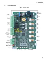
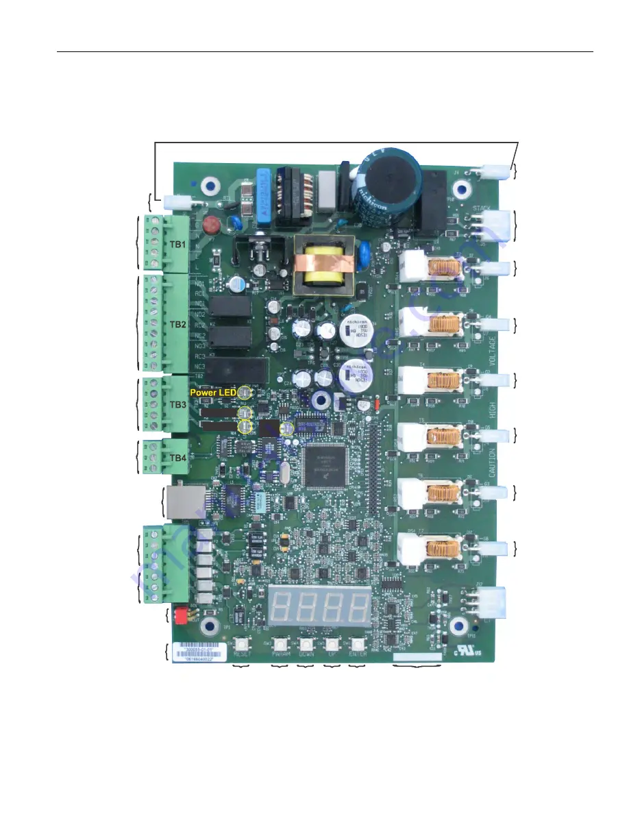
Control Card Layout
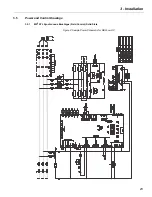
Figure 5: Control Card Layout
Unfused
120 VAC Out
Control
Power
120 VAC
Auxiliary
Relays:
I/O 5-7
(P46-48)
Digital
Inputs:
I/O 1-3
(P42-44)
Modbus
Communications
Port: FUN 10-13
(P66-69)
Keypad Port:
I/O 14 (P55)
Analog Output:
I/O 09-11
(P50-52)
Analog Voltage/Current
Selector Switch SW1
Part/Serial #
Reset
Param
eter
Down Up Enter
Software Part #
120 VAC
Stack In
(Benshaw Only)
Stack
Control
SCR 1
SCR 4
SCR 2
SCR 5
SCR 3
SCR 6
4x7 LED Display
TB5
RJ45
Hall Effect
Transformer
Jumper
RX LED
TX LED
CPU
LED
Summary of Contents for RediStart MX2 SEP
Page 2: ......
Page 8: ...RediStart MX 2 SEP Synchronous Controller User Manual 8 ...
Page 14: ...RediStart MX 2 SEP Synchronous Controller User Manual 14 ...
Page 36: ...RediStart MX 2 SEP Synchronous Controller User Manual 36 ...
Page 52: ...RediStart MX 2 SEP Synchronous Controller User Manual 52 ...
Page 98: ...RediStart MX 2 SEP Synchronous Controller User Manual 98 ...
Page 114: ...RediStart MX 2 SEP Synchronous Controller User Manual 114 ...
Page 116: ...RediStart MX 2 SEP Synchronous Controller User Manual 116 ...
Page 118: ...RediStart MX 2 SEP Synchronous Controller User Manual 118 ...
Page 128: ...RediStart MX 2 SEP Synchronous Controller User Manual 128 ...
Page 129: ...Publication History Revision Date ECO 00 12 15 06 Initial Release 01 12 04 15 E4926 ...


