3.4
RTD Wire Connections
RTD Connections
Each Remote RTD Module has connections for up to 8 RTDs. The terminals for the
RTD wires are as follows;
•
R - RTD return wire.
•
C - RTD compensation wire.
•
H - RTD hot wire.
Each RTD is connected to the three terminals with the common number. For example,
RTD number 5 connects to the terminals numbered 5R, 5C, and 5H.
RTD Cable Specification
Benshaw recommends using 3-wire twisted (triad) shielded cable to connect the RTDs
to the RTD module. It is important to keep the three wires of the same length and
type for accurate lead resistance compensation.
RTD Cable Shielding
The RTD cable shield should be terminated at either of the shield terminals. For a
simpler installation, a cable containing multiple triads with an overall shield can be
used to connect a group of RTDs to the module with a single cable.
3.5
Wiring Diagram
General
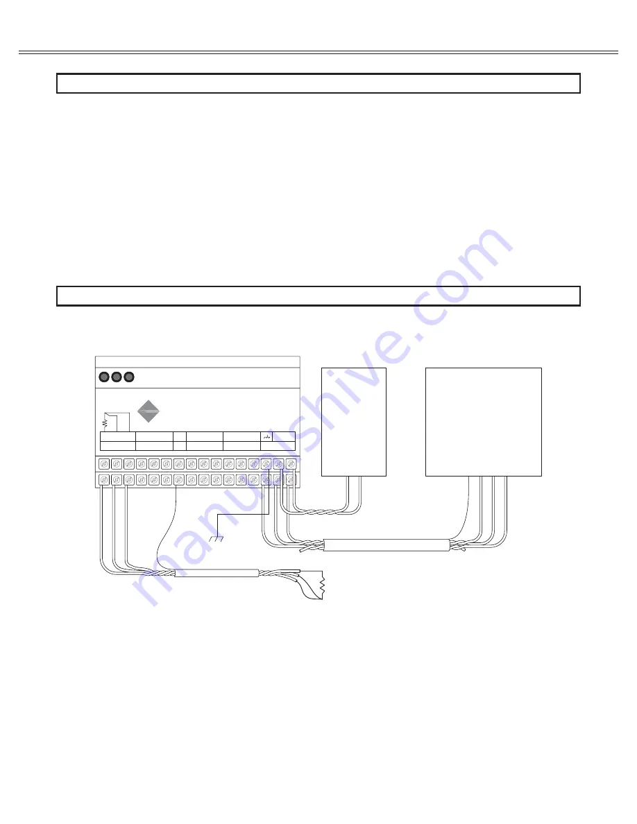
The following is the wiring diagram detailing the connections of the RTD module.
Only the wiring for RTD #5 is shown as the typical connection, but all the other RTDs
connect similarly.
9
3. INSTALLATION OF THE REMOTE RTD MODULE
RTD #5
(Typical)
H
C
R
RS-485 Master
Device
Com
A(-)
B(+)
Shld
24 VDC
Power
Supply
V-
V+
Tx
Rx
Status
8R
8C
8H
7R
7C
7H
6R
6C
6H
5R
5C
5H
Shld
4R
4C
4H
3R
3C
3H
2R
2C
2H
1R
1C
1H
Shld
24 VDC
+
B (+)
A (-)
Com
RS-485
Remote
RTD Module
BENSHAW
ADVANCED CONTROLS & DRIVES


