background image

1

9


e

l

u

d

e

h

c

S


d

e

d

n

e

m

m

o

c

e

R


e

r

u

d

e

c

o

r

P


e

c

a

n

e

t

n

i

a

M


s

t

n

e

n

o

p

m

o

C
Air Filters 

1.

Remove and 

Clean with then  washing  in  lukewarm 


water  (below  40

)  with


neutral soap. 

2.Rinse well to dry before re-installing. 

Note:Never  use  petrol,thinner,benzene  or  any 
other


chemicals.


Every 

1-2


months

More frequently if required. 

Indoor Unit 

1.Clean  away  dirt  or  dust  on  grille  or  panel  by  wiping 

with a soft cloth soaked in lukewarm (or cold) water or 
neutral detergent solution. 

Note:Never  use  petrol,thinner,benzene  or  other 
volatile chemicals,which may cause plastic surface 
to


deform.

Every 2 weeks 
More frequently if required. 

Condensate Drain 
Pan and Pipe 

 .

s

h

t

n

o

m


3


y

r

e

v

E

 .

n

a

e

l

c


d

n

a


k

c

e

h

C

 .

1

 .

y

r

a

s

s

e

c

e

n


s

A

 .

e

s

i

o

n

 l

a

u

s

u

n

u

 r

o

k

c

e

h

C

.

1


n

a

F

 r

o

o

d

n

I
Indoor/OutdoorCoil 

1.Check  and  remove  dirt  which  are  clogged  between 

fins.

2.Check and remove obstacles which hinder air flow in 

and out of indoor/outdoor unit . 

Every 2 months. 

Electrical 

1.Check voltage ,current and wiring. 
2.Check  faulty  contacts  caused  by  loose  connections, 

foreign matters,etc. 

Every 

1

2 months. 

Every 

1

2 months. 

Compressor 

1.No maintenance needed if refrigerant circuit remains 

sealed.However,check  for  refrigerant  leak  at  joints 
and fittings. 

Every 

12

 months. 

Compressor Lubrication 

1.Oil  is  factory  charged  .Not  necessary  to  add  oil  if 

circuit remains sealed. 

No maintenance required. 

Fan Motors Lubrication 

1.All motors pre-lubricated and sealed at factory. 

No maintenance required. 

Tempering 

valve 

strainer

1.Valve function check & strainer cleaning. 

Annually(more  frequently  if 
required) 

Pressure  &  temperature 
relief valve 

1.Pull  the  easing  lever  on  valve  to  ensure  water  is 

relieved to waste through the relief drain pipe. 

Every 6 months 

Sacrificial 

Closed Circuit 

  Anode 

1.Check 

1.Check mixture lever

1.Every month

2.Every 12 months

2.Replace

Circulation Pump

1.Check abnormal noises bearing,Pump is sealed

Every 12 months

type

and replace if Necessary                                       As per tank manufaturers 

                                                                                                                                          recommendations           

7

.SERVICING AND MAINTENANCE

CAUTION:

After installing or servicing the unit, 

please ensure that the front panel is

 secured by the 1 hook undemeath

 the front panel.

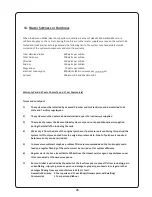
The unit is designed to give a long life operation with minimum maintenance required.However, 

it should be regularly checked and the following items should be given due attention.

Summary of Contents for BENDX ACHW 34

Page 1: ...AIR CONDITIONER WATER HEATER OPERATION MANUAL...

Page 2: ...ury or death Disconnect and lock off power before servicing equipment SPECIAL FEATURES OUTLINES AND DIMENSIONS WIRING DIAGRAMS SAFETY PRECAUTIONS BEFORE INSTALLATION INSTALLATION REMOTE CONTROLOPERATI...

Page 3: ...with refrigerant pipe submerge into water tank ACHW incorporate high efficiency Twin copper tube heat exchanger that circulates the the water in and out of the tank This unique safety feature renders...

Page 4: ...gn filter is slide out type which can be easily removed at the air inlet grille for cleaning WIRELESS REMOTE CONTROL The compact LCD transmitter is able to operate the air conditioner unit within the...

Page 5: ...emperature setting Operation display To set the desined room temperature press the button to increase or decrease the set temperature The temperature setting range is 16 31 C Summer and winter 24 C C...

Page 6: ...60 C Cooling and Hot Water You operate your system as a normal air condi oner and while you are doing so it he ng your hot water for Free ng and Hot Water Because of the unique design of the system th...

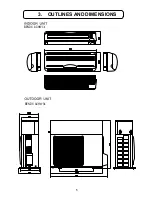
Page 7: ...3 OUTLINES AND DIMENSIONS BENDX ACHW 34 BENDX ACHW 34 5...

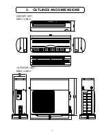
Page 8: ...3 OUTLINES AND DIMENSIONS BENDX ACHW 41 BENDX ACHW 51 BENDX ACHW 41 BENDX ACHW 51 6...

Page 9: ...3 OUTLINES AND DIMENSIONS BENDX ACHW 65 BENDX ACHW 65 7...

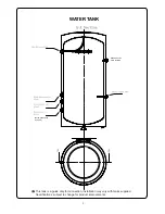
Page 10: ...NK 8 This tank is a guide only for connection installation may vary with tanks supplied Specifications subject to change for product improvements 650kPa P and T Valve Be fitted Recommended filter or s...

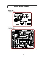
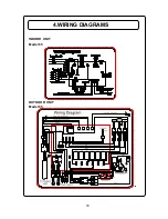
Page 11: ...4 WIRING DIAGRAMS INDOOR UNIT OUTDOOR UNIT Model 34 41 and 51 Model 34 41 and 51 9...

Page 12: ...4 WIRING DIAGRAMS INDOOR UNIT OUTDOOR UNIT Model 65 Model 65 10...

Page 13: ...code Green and yellow Earth Blue Brown Live Neutral As the colours of the wires in the mains lead of this appliance may not correspond with the coloured markings identifying the terminals in your plu...

Page 14: ...fire ignition Confirm drainage piping is connected properly If it is not connected perfectly it may cause water leakag this is the installers Liability and should be checked at commisioning Confirm th...

Page 15: ...6 INSTALATION 13 Cycle Water Inlet Cold Water Inlet Cycle Water Outlet Pressure Regulator Valve is required 500kPa Mixing Valve V 50 C...

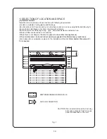
Page 16: ...cooler air can be evenly distributed See fig 1 Ensure that air discharge is not short circuited with air intake Ensure that wall is sufficiently strong rigid flat perpendicular and vibration free Wher...

Page 17: ...in and distribute plenty of air thus lowering the condensing temperature A place capable of bearing the weight of the outdoor unit and isolating noise and vibration A place protected from direct sunl...

Page 18: ...he desired location on the wall and mark the holes location accordingly Ensure that the minimum maintenance and servicing space at the top left and right side of the units is reserved Ensure also the...

Page 19: ...ressor or any moving parts of fan motors The field wires from the indoor unit must be clamped on the wire clamp 4 REFRIGETANT PIPING MODEL PIPE D mm IMPERIAL DLE RIGED DIE A mm 6 35 1 4 1 3 9 52 3 8 1...

Page 20: ...500 microns note R290 connected to Hhandle evacuate to bottle tap Refer to figure at right to connect stop valve gas charging hose mixing valve and vacuum pump Use vacuum pump 76cmHg stop valve liquid...

Page 21: ...ons foreign matters etc Every 12 months Every 12 months Compressor 1 No maintenance needed if refrigerant circuit remains sealed However check for refrigerant leak at joints and fittings Every 12 mont...

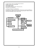
Page 22: ...se of Loose connections Indoor temperature sensor failure E1 Check if sensor is short circuit Indoor pipe temperature sensor failure E2 Check if sensor is short circuit Outdoor system failure E4 Outdo...

Page 23: ...tive 2 Non condensable gases in refrigerant circult e g oil 3 Obstructed air intake discharge 4 Short circuiting of hot air at condensing unit Too low Too high Normal A little Low A little High Data P...

Page 24: ...itioner is disconnected from main power source e Fuse blown or circuit brealer off ii Diagnosis of Refrlgerant Circuit Application There might be some cases where the unit starts running but does not...

Page 25: ...on the flare surface however be very careful not to get any in the inside of the pipe can cause blockages minimal can be used on the thread torque settings still apply The torque Settings liquid 37 N...

Page 26: ...w these may need to be bridge for charging Start the system and continue charging very slowly as the gas maybe sucked in very quickly avoid Liquid refrigerant going directly into the compressor Check...

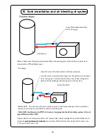
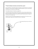
Page 27: ...line lter supplied warranty void if not Cold water in Water is taken from a ng approximately 300mm above the om of the tank and is heated and returned into a ng 100mm lower Air Purging Leave the retur...

Page 28: ...performance will be reduced the system uses the outdoor unit to absorb heat from the atmosphere if the temperature is low the heat absorp on will be less and the hot it is the more heat is absorbed an...

Page 29: ...and all relevant state and territory regulations 10 Defrost deice occurs as the heat pump is absorbing heat from the atmosphere and at low ambient condi ons frost or ice may form The system will autom...

Page 30: ...operated and maintained as per the instruc s supplied 3 The warranty covers the Benson Global system only and not any addi onal parts supplied during the installa on including the tank 4 Warranty is...

Page 31: ...essed in the Warranty Terms and con ons 4 Claims for damages caused directly or indirectly by leakage from the system 5 All damages or breakages is not covered by this warranty and should be added to...

Page 32: ...elow In the event the system has water leaking from the top sec on of the unit a Benson Global authorized agent should be called to check the system Do not a mpt to repair the system yourself this can...

Page 33: ...s that A3 refrigerants R290 shall be permitted only is systems with a refrigerant change of up to 1 5kg for each individual system provided sudden loss of refrigerant could not raise the concentration...

Reviews: