only exception
to this is when a
control panel
suitable for
multiple heater
applications is
supplied by the
manufacturer, in
which case the
wiring diagram
supplied with
the control
panel should be
read in
conjunction with
the existing
wiring diagram.
Any ancillary electrical items e.g. room
thermostats , time switches, remote panels
etc, must be wired into the heater electrical
circuit in accordance with the diagrams
provided
Note
When external controls operate to
switch the heater OFF, power to the heater
should remain to allow the fan to continue to
operate to sufficiently cool the heater thereby
preventing damage to the heat exchanger.
2.8 Time switch
Caution
Time switches may only be fitted if they are
of an approved type, and must have
separate motor connections, the motor must
be connected to a suitable live and neutral
supplies, and with the switching contacts
then wired in series from the neutral side of
the room thermostat to terminal 7
Reference should be made to the wiring
diagrams contained with the time switch, and
within section 6.0 of this manual
2.9 Room thermostat
Any external room thermostat should be
fitted with the common terminal (if fitted with
changeover contacts) to terminal 5.
If the thermostat is fitted with a heat
anticipator this should be fitted to terminal 2.
The thermostat should be mounted at a
height of approximately 1.5mm from the floor
in an area where the ambient temperature is
representative of the area to be heated. The
siting of the room thermostat should be in a
draught free area. or in an area where
temperatures are free from the influences of
direct sunlight or heated discharged air.
2.10 Fan limit control
( Situated inside the right hand side panel)
Fan control
(white button)
The fan control switch features normally
open 230V contacts, and is wired to control
the live supply to the fan motor . When the
circuit is made, the fan will switch on when
the heat anticipator has closed the fan switch
contacts. When the thermostat or time switch
shuts down the burner, the fan will continue
to run until the thermal switch has cooled
sufficiently to prevent the residual heat from
damaging the heater or its controls.
On startup the fan delay prevents air being
circulated until the desired temperature is
achieved
Limit control
(red button)
An adjustable high temperature manual reset
limit control. If this control needs resetting the
cause should be determined and rectified
immediately.
On models with two fans a second limit
Summary of Contents for GUHA
Page 6: ......
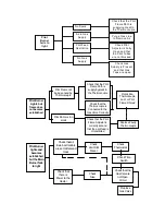
Page 26: ...GUH 50 to 165 Piezo Ignition 6 0 Wiring Diagrams GUH 205 325 Piezo Ignition...
Page 27: ...GUH 400 408 Piezo Ignition GUH 50 325 Automatic Ignition...
Page 28: ...GUH 400 480 Automatic Ignition T CP 2 Control GUH 50 325 Piezo ignition...
Page 29: ...CP 2 Control GUH 50 325 Auto reset CP 2 Control GUH 400 480 Auto reset...
Page 30: ...CP4 Control GUH 400 480 CP 4 Control GUH 50 325...

