background image

MODEL    NATURAL 

GAS 


GUH50 


GUH75 


GUH100 


GUH125 


GUH165 


GUH205 

HEAT        

  OUTPUT 

kW 
Btu 

15.2 

51,900 

22.0 

75,000 

29.3 

100,000 

37.0 

126,250 

48.4 

165,140 

61.6 

210,180 

HEAT         INPUT  

(Gross) 

kW 
Btu 

20.1 

68,600 

28.2 

96,200 

37.5 

128,000 

47.6 

162,500 

62.3 

212,600 

79.2 

270,300 

MINIMUM INLET 

PRESSURE 

mbar 

Ins WG 

17.5 

17.5 

17.5 

17.5 

17.5 

17.5 

BURNER            

PRESSURE 

mbar 

Ins WG 

13.2 

5.3 

13.0 

5.2 

6.5 
2.6 

7.1 
2.8 

7.4 
3.0 

7.4 
3.0 

NAT  GAS  

CONSUMPTION 

ft

3

/hr 

m

3

/hr 

66.6 

1.9 

93.4 
2.65 

124.3 

3.5 

157.8 

4.5 

206.3 

5.85 

262.5 

7.45 

TEMPERATURE       

RISE 

ºC 

ºF 

28 
82 

34 
93 

33 
91 

32.6 

90 

32.5 

90 

33 
91 

AIR                            

FLOW 

ft

3

/min 

m

3

/sec 

934 

0.441 

1114 

0.526 

1528 

0.721 

1860 

0.878 

2485 

1.173 

3060 

1.444 

AXIAL FAN          

THROW 

ft 

mtrs 

35 

10.9 

40 

12.4 

50 

15.5 

55 

17.1 

65 

20.2 

65 

20.2 

CENTRIFUGAL FAN 

STATIC PRESSURE 

Pa 

Ins WG 

75 

0.3 

100 

0.4 

100 

0.4 

125 

0.5 

163 

0.65 

125 

0.5 

SOUND LEVEL 

Dba 

57 

63 

63 

69 

72 

72 

GAS CONNECTION 

BSP 

3/4 

3/4 

3/4 

3/4 

3/4 

3/4 

MAIN INJECTOR 

NATURAL GAS 

mm 

No Off 

1.8 

1.8 

2.6 

2.6 

2.6 

2.6 

10 

FLUE DIAMETER 

mm 

125 

125 

150 

175 

200 

200 

ELECTRICITY SUPPLY 


230/1/50  230/1/50  230/1/50  230/1/50  230/1/50  230/1/50 

ELECTRICAL POWER 

(AMPERES) 

Axial 
Cent 

0.4 

0.8 

0.8 

1.5 

1.7 

2.0 

FUSE RATING Axial 

Amps 

POWER ABSORPTION 

Kw 

Axial 
Cent 

0.1 
0.4 

0.15 
0.63 

0.15 
0.63 

0.36 
0.85 

0.36 
1.05 

0.3 

1.26 

AIR OUTLET 

VENTILATION AREA 

cm

2


in

90 
14 

127 

20 

169 

26 

215 

34 

275 

43 

313 

49 

MOUNTING HEIGHT 

(MTRS) 

Min 

Max 

1.82 
2.73 

1.82 
2.73 

2.12 
3.03 

2.42 
3.33 

2.73 
3.94 

2.73 
3.94 

GROSS FLUE TEMP 

ºC 

170 

180 

170 

180 

170 

180 

WEIGHT                        

Kgs 

Axial 
Cent 

70 
81 

88 

101 

107 
120 

123 
136 

155 
175 

188 
216 

7.2  Unit Heater Models Technical Data 

Summary of Contents for GUHA

Page 1: ...r maximum i mpact use two or thr ee sentences Headin g BENSON GUHA GUHC RANGE NATURAL GAS FIRED UNIT HEATER I N S T A L L A T I O N C O M M I S S I O N I N G S E R V I C I N G U S E R I N S T R U C T...

Page 2: ...l Installation 2 7 Electrical Panel 2 8 Time Switch 2 9 Room Thermostat 2 10 Fan and Limit Controls 2 11 Summer Ventilation Switch 2 12 Gas Installation 3 0 Commissioning 3 1 Electrical Pre Tests 3 2...

Page 3: ...orm part of the heater or burner assembly from potential pipe contamination particularly but not exclusively where copper gas pipework is used In instances where copper pipework is to be used for all...

Page 4: ...customers with a comprehensive information pack this clearly defines mandatory instructions for the safe installation use and maintenance of the appliance s Where proprietary items are incorporated in...

Page 5: ...d methods of measurement of radio disturbance characteristics of electrical motor operated and thermal appliances for household and similar purposes electrical tools and similar electric apparatus BS...

Page 6: ......

Page 7: ...anufactured from aluzinc coated steel and is located beneath the clam The complete burner rack is easily withdrawn through the front of the heater Standard heaters are supplied suitable for Natural Ga...

Page 8: ...tive to the supply of fresh air f The position of the heater relative to potential stratification circulation problems which generally occur at higher levels and which may be overcome through the prov...

Page 9: ...allation details name and address 4 Details or symptoms of fault 5 Installers name and address Faulty parts must be returned to the Benson Heating Spares Department the address of which is provided on...

Page 10: ...re adjusted outwards and ensure blades are not resonating sources of cold air ingress and obstructions The air temperature rise on passing the heat exchanger is typically around 340 C A full and unobs...

Page 11: ...an automatic control interlocked to the burner must be fitted to ensure burner shutdown in the event of airflow failure or restriction When the area to be heated already has an extraction system the s...

Page 12: ...to flow freely to a point from which they may be released preferably into a gully The condensate pipe from the flue to the disposal point must be made from corrosion resistant pipe of not less than 2...

Page 13: ...s than 10 h1 Fig 3 Flat roof envelope method Structure Not less than 250mm 2 Greater than 10 h1 H1 H2 Structure Fig 4 Flat roof where the flue height is more than 10 Heights H away from all structures...

Page 14: ...ith structure close to flue outlet Not less than 600mm Not greater than 45 Not less than 600mm Fig 8 Pitched roof not greater than 45 Less than 1500mm Dormer window Not less than 600mm Fig 9 Pitched r...

Page 15: ...exceeding 45 Less than 45 Not less than 600mm Termination on ridge Fig 11 Pitched roof internal route not exceeding 45 and ridge termination Fig 12 Pitched roof chimney within 1 5m from dormer window...

Page 16: ...orrect supply connection points for the live neutral and earth are clearly indicated on the wiring diagram mounted inside the wiring box cover Wiring diagrams are also detailed within this manual sect...

Page 17: ...with the common terminal if fitted with changeover contacts to terminal 5 If the thermostat is fitted with a heat anticipator this should be fitted to terminal 2 The thermostat should be mounted at a...

Page 18: ...2 12 Gas installation Warning As there have been recorded instances of the deposition of copper sulphide dust within the valves and orifices of gas appliances as a direct result of a reaction between...

Page 19: ...n which must be sited outside the heater the isolating cock should be of the 900 turn type and should be clearly marked OPEN CLOSED it should also be installed so as to fall to the closed position An...

Page 20: ...t all panels and fasteners are secure and in place b Check that the heater is mounted safely c Check that the flue is sealed secured and adequately supported d Check that the fan is free to rotate tha...

Page 21: ...even stable and conical o Check pressure readings on the manometers and continue to let the heater fire for ten minutes p When the fan starts ensure that the direction of rotation is correct and that...

Page 22: ...the user should be made aware of the most efficient and economical methods of operation The user must be familiar and satisfied with the safety ignition shutdown and general operational procedures 4 0...

Page 23: ...at the Pilot Flame Path is supplying Heat to the Thermocouple Pilot Flame is too small Check that the Thermocouple is Connected to the Gas Valve Correctly Check that the Pilot Flame Adjuster is correc...

Page 24: ...ect Purge System to Remove Air Check that Pilot Adjuster is set Correctly Check Gas taps are open and Gas is Present Check Electrode is not Cracked Check HT leads and C t Check Spark Generator Check C...

Page 25: ...pen Circuit Check that Fan will run when Main Gas is On Replace Faulty Fan Control Open Circuit to Fan Motor Check Wiring and Connections Fan runs but stops when Main Burner is alight Faulty Motor Fan...

Page 26: ...GUH 50 to 165 Piezo Ignition 6 0 Wiring Diagrams GUH 205 325 Piezo Ignition...

Page 27: ...GUH 400 408 Piezo Ignition GUH 50 325 Automatic Ignition...

Page 28: ...GUH 400 480 Automatic Ignition T CP 2 Control GUH 50 325 Piezo ignition...

Page 29: ...CP 2 Control GUH 50 325 Auto reset CP 2 Control GUH 400 480 Auto reset...

Page 30: ...CP4 Control GUH 400 480 CP 4 Control GUH 50 325...

Page 31: ...et calorific valueof the gas at 1013 mbar and 15o C dry in MJ m3 Hs is the gross calorific value of the gas at 1013 mbar and 15o C dry in MJ m3 Vf is the volume of dry products of combustion per unit...

Page 32: ...12 4 50 15 5 55 17 1 65 20 2 65 20 2 CENTRIFUGAL FAN STATIC PRESSURE Pa Ins WG 75 0 3 100 0 4 100 0 4 125 0 5 163 0 65 125 0 5 SOUND LEVEL Dba 57 63 63 69 72 72 GAS CONNECTION BSP 3 4 3 4 3 4 3 4 3 4...

Page 33: ...20 2 70 21 7 CENTRIFUGAL FAN STATIC PRESSURE Pa ins WG 125 0 5 163 0 65 163 0 65 150 0 6 163 0 65 SOUND LEVEL Dba 72 70 70 72 73 GAS CONNECTION BSP 3 4 3 4 3 4 2 x 3 4 2 x 3 4 MAIN INJECTOR NATURAL GA...

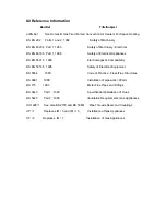
Page 34: ...tromagnetic Compatibility BS EN 50165 1995 Safety of Electrical Equipment BS 5854 1980 Code of Practice Flues Flue Structures BS 6891 1988 Installation of pipework 28mm BS 715 1993 Metal Flue Pipes an...

Page 35: ...48 common common common common common Pilot Injector 28 90 153 common common common common common Thermocouple 33 50 004 common common common common common Ignition Electrode 28 90 156 common common c...

Page 36: ...Valve Honeywell 28 30 114 28 30 103 28 30 103 28 30 114 28 30 114 Pilot Burner c w shear olive 28 90 148 common 28 90 148 common 28 90 148 Pilot Injector 28 90 153 28 90 153 common 28 90 153 common T...

Page 37: ...s or poor workmanship within twelve months from the despatch date of the heater will be repaired or replaced free of charge inclusive of parts and labour 3 Any part manufactured by Benson Heating whic...

Page 38: ...ment the instruction s can lead not only to component damage but can also lead to a hazardous situation being created where there is a risk of personal injury or death 10 1 Commissioning and hand over...

Page 39: ...control is by way of a Satronic controller with automatic gas valve replacing the manual standing pilot valve used in conjunction with a Satronic spark generator which replaces the piezo igniter as fi...

Page 40: ...ating Ludlow Road Knighton Powys LD7 1LP Telephone 01547 528534 Facsimile 01547 520399 Email information bensonheating co uk Web www bensonheating com Benson Heating is a Division of Benson Climate Sy...

Reviews: