1701ULTRA(EC)GBEN, p. 10/29
6
INSTALLING
WARNING
Check
the
supporting
structure
to
verify
that
it
has
sufficient
load
‐
carrying
capacity
to
support
the
unit
weight.
Suspend
the
heater
only
from
the
threaded
nut
inserts.
Do
not
suspend
from
the
heater
cabinet
panels.
Do
not
place
or
add
additional
weight
to
the
suspended
heater.
The
location
where
the
air
heater
is
to
be
installed
must
provide
sufficient
space
around
the
heater
for
servicing
and
clearances
for
safety
(see
figure
2).
When
the
unit
is
lifted
for
suspension,
leave
the
unit
on
the
pallet.
Before
hanging
verify
that
all
screws
originally
used
to
fix
the
shipping
supports
are
re
‐
screwed
into
the
cabinet.
Ensure
that
the
heater
is
installed
in
a
level
plane
and
vibration
free.
The
air
heater
must
be
fastened
securely
to
any
base
mounting
arrangement.
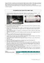
The
heater
is
supplied
with
four
point
suspension.
All
points
must
be
used.
Threaded
nut
inserts
are
provided
on
each
side
of
the
top
of
the
heater.
See
figure
4.
After
suspension
the
air
heater
should
be
rigid
so
as
to
avoid
placing
a
strain
on
the
flue
system,
gas
services,
electrical
wiring
and
duct
work.
1”
BSP
mounting
cap
nuts
are
optional.
In
case
of
a
type
C
installation,
the
distance
between
the
floor
and
the
underside
of
the
air
heater
must
be
at
least
1.70m.
Combustion
air
should
be
taken
from
a
height
that
exceeds
the
above
mentioned
height
of
1.70m.
Also
thermostats
and
switches
which
are
not
sparkless
have
to
be
installed
at
a
minimum
height
of
1.70m.
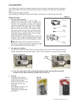
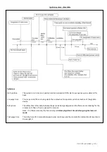
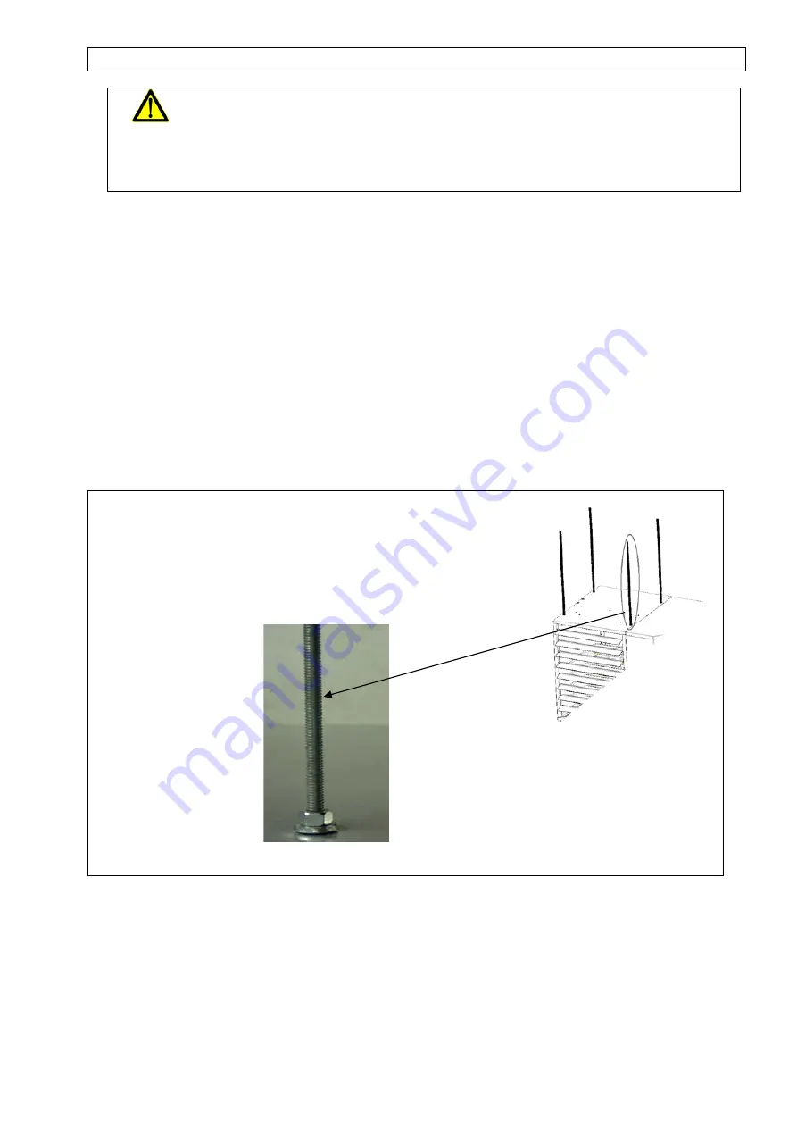
Figure
4
Be
sure
that
the
threaded
hanger
rods
are
locked
to
the
heater
as
illustrated
in
this
figure.
Recommended
maximum
hanger
rod
length
is
1.8m.
Where
longer
drops
are
required,
ensure
that
restraints
are
fitted
to
prevent
excess
lateral
movement
and
supports
are
adequately
sized.
Alternatively
the
unit
can
also
e
base
mounted
on
a
non
‐
combustible
support.
In
this
case
ensure
that
unit
is
securely
fixed
on
the
base.


