1701ULTRA(EC)GBEN, p. 11/29
7
AIR
SUPPLY
&
FLUE
SYSTEM
7.1
GENERAL
WARNING
The
flue
must
be
in
accordance
with
all
international
and
national
rules
and
regulations
in
force.
Local
requirements
may
apply
in
addition
to
national
requirements.
Failure
to
provide
proper
flueing
could
result
in
death,
serious
injury
and/or
property
damage.
The
products
of
combustion
must
be
flued
to
outside
atmosphere.
Common
flues
(for
more
than
one
appliance)
must
not
be
used.
Single
wall
flue
pipe
exposed
to
cold
air
or
run
through
unheated
areas
should
be
insulated
to
avoid
condensation.
If
the
flue
passes
through
a
combustible
element
of
the
building
it
must
be
enclosed
by
a
sleeve
of
non
‐
combustible
material
and
separated
from
the
sleeve
by
at
least
a
25mm
air
break.
The
temperature
of
any
combustible
material
near
to
the
flue
must
not
exceed
65°C
when
the
heater
is
in
operation.
The
flue
must
be
at
least
50mm
away
from
any
combustible
material.
Provision
must
be
made
for
condensation
to
flow
freely
to
a
point
to
which
it
can
be
released,
i.e.
drain.
M
odel
ULTRA/ULTRA
EC
heaters
may
be
installed
as
type
B
or
type
C
installations.
The
unit
heaters
are
designed
to
operate
safely
and
efficiently
with
either
a
horizontal
or
vertical
flue
system
when
installed
according
to
the
specific
requirements
and
instructions.
If
this
heater
is
replacing
an
existing
heater,
be
sure
that
the
flue
is
of
the
correct
size
and
that
the
existing
flue
is
in
good
condition.
A
correctly
sized
flue
system
is
required
for
safe
operation
of
the
heater.
An
improper
sized
flue
system
can
cause
unsafe
conditions
and/or
create
condensation.
The
units
may
be
installed
as
a
balanced
flue
type
C
heater
requiring
both
a
combustion
air
inlet
pipe
and
a
flue
pipe
or
as
a
power
vented
heater
type
B
where
the
combustion
air
is
taken
from
the
space
where
heater
is
installed
and
which
requires
only
a
flue
pipe
exhausting
to
outdoors.
All
products
of
combustion
must
be
flued
to
outdoor
atmosphere.
E
ach
heater
installed
as
a
type
B
appliance
must
be
fitted
with
an
individual
flue
pipe
and
the
combustion
air
inlet
opening
must
be
provided
with
a
protection
grill.
E
ach
heater
installed
as
a
type
C
appliance
must
be
fitted
with
an
individual
combustion
air/flue
pipe
system.
Type
C2
appliance,
with
single
pipe
system
for
supply
of
combustion
air
and
evacuation
of
flue
gasses,
are
not
allowed.
For
testing,
the
flue
pipe
should
include
a
sealable
test
point.
Ideally
the
test
point
should
be
at
least
450mm
away
from
the
air
heater
flue
connection
socket.
However
if
a
concentric
flue
is
attached
directly
to
the
connection
sockets
then
the
combustion
should
be
tested
through
the
flue
outlet
collar
via
a
drilled
test
point
which
must
be
securely
plugged
on
completion.
F
ollow
the
flue
pipe
manufacturer’s
installation
instructions
for
making
joints,
including
connections
to
the
air
heater,
for
passing
through
a
building
element
and
for
support
requirements.
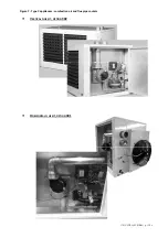
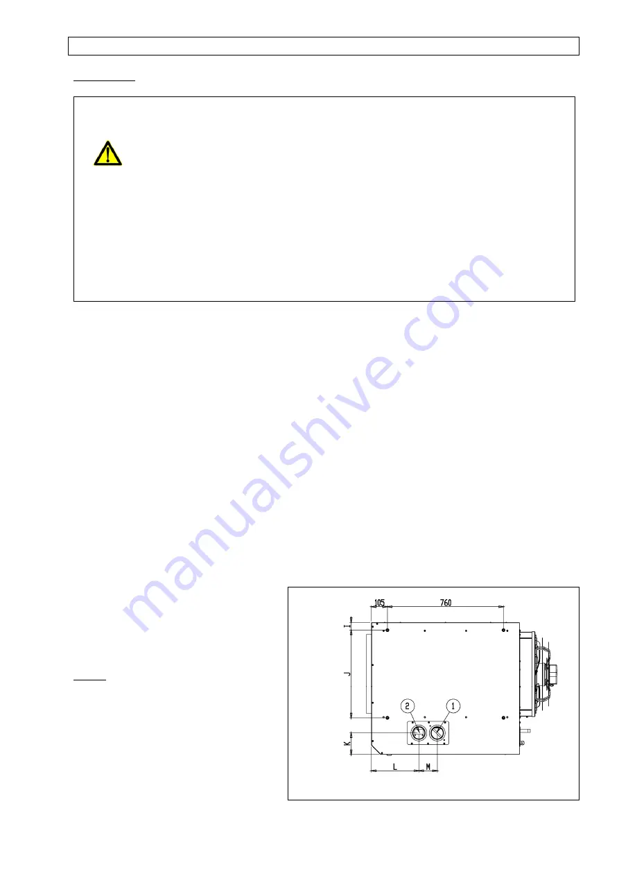
Figure
5
:
Combustion
air
and
flue
pipe
sockets
(standard
version)
Remark
:
A
cover
plate
can
be
installed
on
the
rear
or
top
panel.
The
plate
with
the
fresh
air
inlet
and
the
flue
outlet
socket
is
factory
installed
on
the
top
panel
but
can
easily
be
replaced
on
the
rear
panel
if
required.
In
case
of
change,
a
separate
kit
must
be
ordered
at
the
supplier.
Combustion
air
inlet
Flue
connection


