1701ULTRA(EC)GBEN, p. 16/29
9
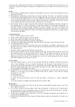
GAS
SUPPLY &
GAS
CONNECTION
We
refer
to
table
1
of
section
3
for
all
gas
specifications
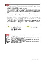
WARNING
Connection
to
a
gas
service
installation
may
only
be
carried
out
by
suitably
qualified
persons.
The
gas
installation
must
comply
with
all
rules
in
force.
Only
materials
appropriate
for
gas
service
installation
may
be
used.
Do
not
rely
on
the
heater
to
support
the
gas
pipe.
NEVER
USE
A
FLAME
TO
TEST
FOR
GAS
SOUNDNESS.
ALL
COMPONENTS
OF
A
GAS
SUPPLY
SYSTEM
MUST
BE
LEAK
TESTED
PRIOR
TO
PLACING
EQUIPMENT
IN
SERVICE.
FAILURE
TO
COMPLY
COULD
RESULT
IN
PERSONAL
INJURY,
PROPERTY
DAMAGE
OR
DEATH!
9.1
GENERAL
ULTRA/ULTRA
EC
heaters
are
designed
to
operate
on
either
natural
gas
(G20),
propane
(G31)
or
butane
(G30)
gas.
Check
that
gas
supply,
gas
category
&
gas
inlet
pressure
is
in
accordance
with
the
data
described
on
the
air
heater
.To
let
the
unit
function
at
maximal
heat
output,
the
gas
supply
pipe
MUST
be
correctly
sized.
Close
to
the
air
heater
a
gas
tap
with
coupling
must
be
mounted
for
servicing
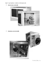
(see
figure
11).
It
is
strongly
recommended
to
place
a
gas
filter
and
clean
the
gas
tube
with
nitrogen.
The
whole
of
the
gas
service
installation
including
the
meter
must
be
inspected,
tested
for
soundness
and
purged
in
accordance
with
appropriate
requirements
by
a
qualified
person.
9.2
GAS
CONNECTION
9.3
ADJUSTMENT
GAS
VALVE
To
adjust
the
offset,
remove
the
protection
screw
on
the
top
and
regulate
the
offset
by
using
the
exposed
screw.
Offset
values
will
be
measured
in
the
indicated
points.
To
adjust
the
CO
2
,
use
a
screwdriver
in
the
indicated
spot
and
turn
the
screw
driver
clockwise
to
decrease
the
measured
CO
2
or
turn
it
counter
clockwise
to
increase
the
measured
CO
2
.
The
CO
2
measurement
should
be
done
in
the
flue
discharge
pipe.
A
ll
units
are
set
according
to
the
data
plate
before
leaving
the
factory.
Any
modification
to
the
gas
valve
must
be
done
by
a
qualified
technician.
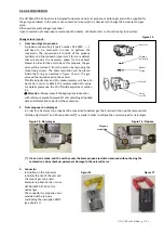
1
h
2
Inlet
pressure
measuring
point
3
CO2
adjustment
point
(throttle
)
4
Offset
measuring
point
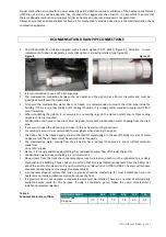
REMARK
:
Do
not
over
tighten
and
do
not
rotate
the
gas
valve
inside
the
heater
control
compartmen
Figure
12
Figure
11


