1701ULTRA(EC)GBEN, p. 18/29
10
ELECTRICAL
SUPPLY
&
CONNECTIONS
10.1
ELECTRICAL
SUPPLY
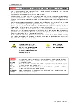
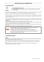
DANGER
THIS
APPLIANCE
MUST
BE
EARTHED.
The
electrical
installation
may
only
be
carried
out
by
suitably
qualified
persons
observing
the
rules
in
force.
Check
that
the
electrical
specifications
are
in
accordance
with
the
data
on
the
air
heater.
All
electrical
connections
should
be
in
accordance
with
the
terminal
markings
and
the
wiring
diagram
affixed
to
the
air
heater.
The
minimum
external
controls
required
for
the
air
heater
are
a
room
thermostat.
It
is
essential
that
the
main
input
line
and
neutral
to
terminals
L
and
N
remains
live
at
all
times
even
when
the
appliance
is
switched
off,
this
is
to
ensure
correct
operation
of
the
unit.
The
minimum
clearance
distance
between
the
contacts
must
be
more
than
3mm.
Check
that
the
air
heater
is
well
earthed
and
that
an
earth
leakage
test
is
carried
out.
The
electrical
supply
line
to
the
heater
should
include
a
main
isolating
switch.
An
external
orange
indicator
light
is
fitted
on
the
heater
to
signify
when
the
burner
is
ON.
An
external
burner
reset
switch
with
red
indicator
light
is
fitted
on
the
heater.
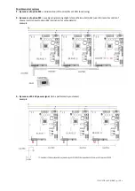
To
add
a
remote
reset
button,
make
connections
to
the
terminals
in
the
electric
box
as
indicated
on
the
wiring
diagram.
Ensure
that
all
cables
and
installers
wiring
are
appropriately
fixed
and
that
they
do
not
touch
the
flue
combustion
collector
box.
To
ensure
that
the
unit
is
airtight,
all
unused
cable
couplings
must
be
hermetically
sealed.
Attention
‐
Permanent
damage
can
occur
to the burner
relay
when
faulty/incorrect
connections
to
the
thermostat,
reset
switch
or
burner
failure
lamp
are
made!
‐
Switching
of
wires
for
reset
switch
and
flame
failure
will
destroy
the
burner
relay.
‐
If
the
reset
button
requires
activating
for
any
reason,
the
cause
must
be
determined.
After
determining
and
correcting
the
problem,
restart
the
heater
and
monitor
long
enough
to
ensure
proper
operation
(approx.
5
minutes).
10.2
THERMOSTAT
LOCATION
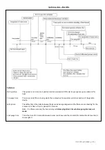
General
Do
not
attempt
to
control
more
than
1
heater
from
a
single
thermostat
or
control
panel
unless
a
properly
wired
relay
is
fitted.
Follow
the
instructions
supplied
with
such
panels.
The
location
of
the
room
thermostat
or
sensor
is
very
important.
It
should
not
be
positioned
on
a
cold
wall
or
cold
surface.
Avoid
location
in
draughty
areas
or
where
it
may
be
influenced
by
heat
sources
e.g.
the
sun,
process
plant,
etc...
The
thermostat
should
be
mounted
on
a
vibration
free
surface
and
mounted
about
1.5m
above
floor
level.
Follow
the
thermostat
manufacturer’s
instructions.


