1701ULTRA(EC)GBEN, p. 9/29
4.2
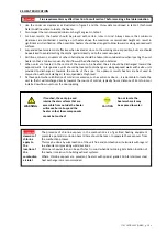
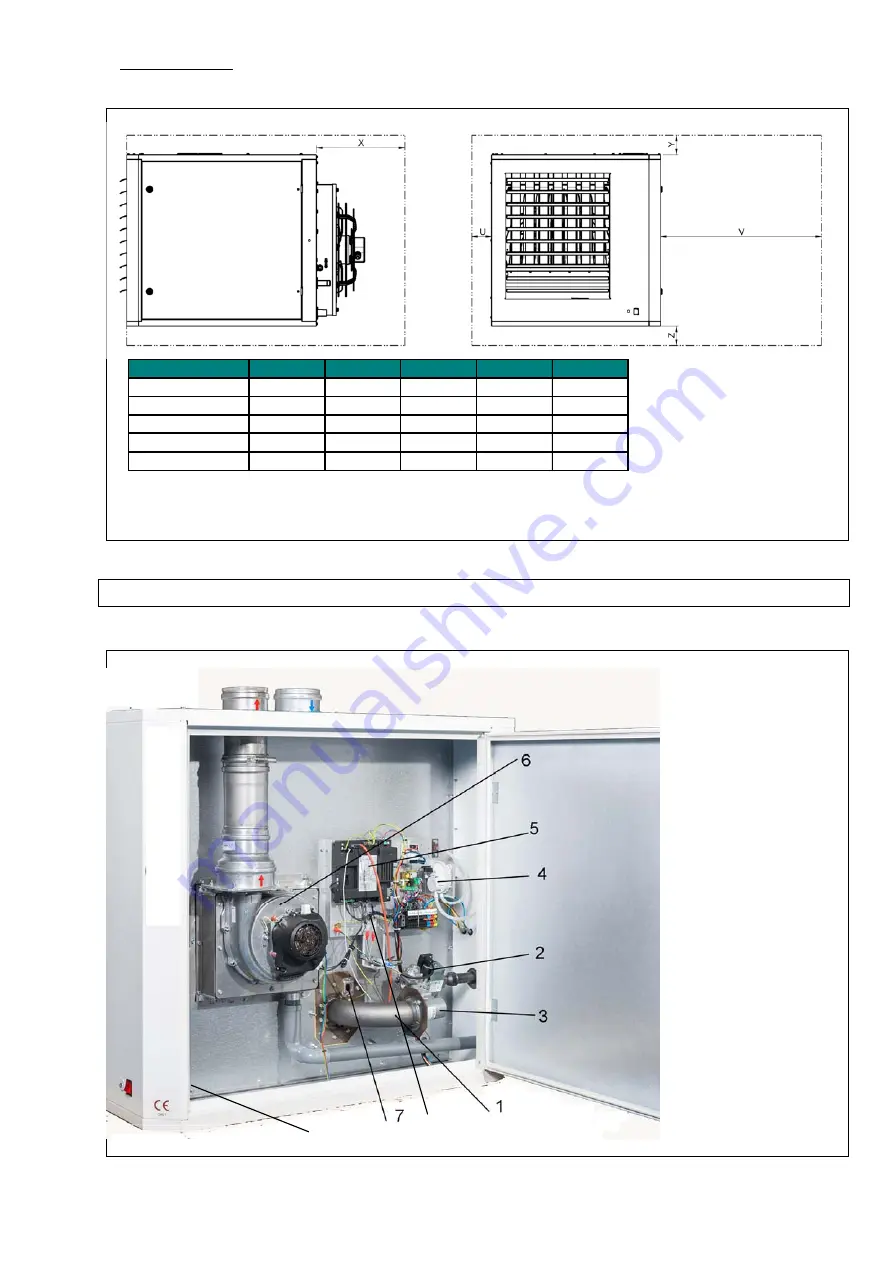
CLEARANCES
Figure
2
:
ULTRA/ULTRA EC
X
Y
Z(*)
U
V
025
400
100
100
100
820
035
400
100
100
100
820
050
400
100
100
100
820
075
500
100
100
100
820
100
500
100
100
100
820
(*)
Heaters
can
be
mounted
on
suitable
non
‐
combustible
supports.
5.
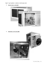
INTERNAL
LAYOUT
Figure
3
:
1
Metal
mesh
burner
2
Zero
pressure
regulator
3
Venturi
4
Differential
pressure
switch
5
Burner
controller
6
Flue
gas
extraction
fan
7
Inspection
window
+
ionisation
electrode
8
Limit
control
LC3
9
Limit
control
LC1
9
8


