1704VRC3-AMEN, p 16/35
GENERAL
REQUIREMENTS
3.1
Related
documents
It
is
important
that
all
gas
appliances
are
installed
in
accordance
with
the
rules
in
force
and
by
appropriately
qualified
persons.
Failure
to
install
appliances
correctly
could
lead
to
prosecution.
It
is
in
your
own
interest
and
that
of
safety
to
ensure
compliance
with
the
law.
Air
heaters
should
not
be
installed
in
corrosive
atmospheres,
i.e.
near
plating
or
degreasing
plants
or
in
areas
where
there
is
a
fire
risk.
Do
not
locate
the
air
heater
where
it
may
be
exposed
to
water
spray,
rain,
etc.
3.2
Heater
location
The
location
chosen
for
the
air
heater
must
permit
the
provision
of
a
satisfactory
flue
system
venting
to
outdoor
atmosphere
and
adequately
ventilated
to
provide
for
combustion
air.
The
location
must
also
provide
sufficient
space
to
allow
the
heater
to
be
serviced.
Table
3
Minimum
installation
clearances
(mm)
Table
4 Recommended mounting
heights
(m)
(*)
*
Measure
rear
clearance
from
the
back
of
the
motor
*
Height
from
floor
to
bottom
surface
of
heater.
These
are
recommendations
only.
Positioning
of
heaters
depends
on
application.
Air
heaters
should,
where
ever
possible
always
be
installed
to
blow
toward
or
along
external
wall
surfaces.
Where
two
or
more
air
heaters
are
installed
in
the
same
room,
a
general
scheme
to
ensure
continuous
air
circulation
should
be
maintained
for
best
results.
Suspended
heaters
are
most
effective
when
located
as
close
to
the
occupancy
zone
as
possible,
this
fact
should
be
born
in
mind
when
determining
the
mounting
heights
to
be
used.
Care
should
be
exercised
to
avoid
directing
warm
air
directly
onto
the
occupants.
Partitions,
columns,
counters,
storage
racking,
etc.
should
be
taken
into
account
when
choosing
the
location
so
that
an
unobstructed
path
for
the
air
circulation
can
be
maintained.
Where
air
heaters
are
located
in
the
centre
of
the
space
to
be
heated,
the
air
should
be
discharged
toward
outside
walls.
In
large
areas,
they
should
be
located
to
discharge
air
along
outside
walls
with
additional
heaters
provided
to
blow
air
into
the
centre
of
the
area.
In
places
where
infiltration
of
cold
is
excessive,
such
as
entrance
doors
it
is
desirable
to
locate
a
heater
so
that
warm
air
is
discharged
directly
toward
the
source
of
cold
air
from
a
distance
of
4,5
‐
6,0
metres.
3.3
Combustion
air
supply
&
flue
system
The
air
heater
may
be
installed
as
a
balanced
flue
(Type
C)
heater
requiring
both
a
combustion
air
inlet
duct
and
a
flue
pipe
or
as
a
power
vented
(Type
B)
heater,
which
requires
only
a
flue
pipe
exhausting
to
outdoors.
All
products
of
combustion
must
be
flued
to
outdoor
atmosphere.
Each
heater
installed
as
a
type
B
appliance
must
be
fitted
with
an
individual
flue
pipe
and
the
combustion
air
inlet
opening
must
be
provided
with
a
protection
grill
(ask
your
distributor
for
the
appropriate
protection
grill
(IP20)
(dia130
=
PN
02
25094
).
Each
heater
installed
as
a
type
C
appliance
must
be
fitted
with
an
individual
combustion
air/flue
pipe
system.
Only
systems
specified
by
the
air
heater
manufacturer
may
be
used.
Common
flue
and
combustion
air
systems
must
not
be
used!
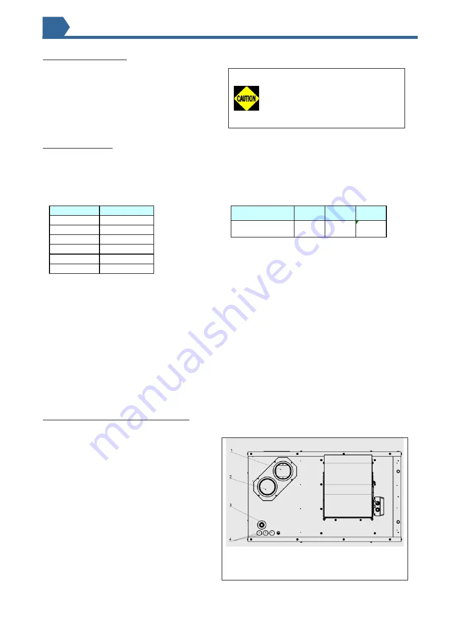
Figure
2a
:
Combustion
air
and
flue
pipe
sockets
1
Flue
outlet
socket
2
Combustion
air
inlet
opening
3
Gas
connection
inlet
with
sealing
ring
4
Electrical
connections
3
VRC-3
20
30
45
others
Mounting height
3
4
5
VRC-3
100
Top
150
Flue connector
150
Access panel
500
Non access sid
150
Bottom
150
Rear*
250
Summary of Contents for VRC-3 100-3
Page 5: ...1704VRC3 AMEN p 5 35 VRC 30 3 VRC 45 3 ...
Page 6: ...1704VRC3 AMEN p 6 35 VRC 60 3 VRC 75 3 ...
Page 8: ...1704VRC3 AMEN p 8 35 VRC 30 3 with mix box VRC 45 3 with mix box ...
Page 9: ...1704VRC3 AMEN p 9 35 VRC 60 3 with mix box VRC 75 3 with mix box ...
Page 11: ...1704VRC3 AMEN p 11 35 VRC 30 3 with mix box and filters VRC 45 3 with mix box and filters ...
Page 12: ...1704VRC3 AMEN p 12 35 VRC 60 3 with mix box and filters VRC 75 3 with mix box and filters ...
Page 14: ...1704VRC3 AMEN p 14 35 2 5 Dimensions STANDARD UNIT ...
Page 15: ...1704VRC3 AMEN p 15 35 UNIT WITH MIXING CABINET option 526 ...


