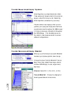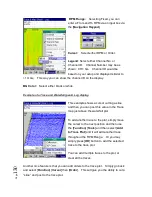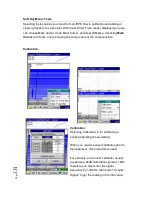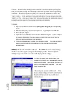
P
ag
e
118
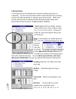
Channel Setup
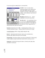
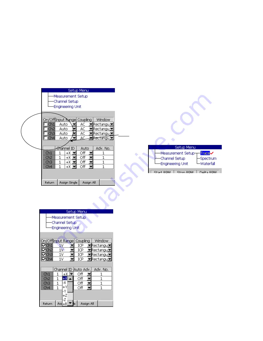
The Channel Setup is for defining each channel according to what you are
measuring. You can turn each channel On/Off, select the Input range, Coupling,
window, and other parameters for making a good measurement. Please note
that the channel setup is relational between the Measurement Setup-Trace,
Measurement Setup- Spectrum, and Measurement- Waterfall.
Input range
:
Select Auto Range, Up Only,
10mV, 20 mV, 50 mV, 100 mV, 200 mV, 500
mV, 1 V, 2V, 5V. 10V, or 20V.
This should
match the output of the device that you are
connecting to.
Note
- In this example, the On/Off selector for
Ch1, Ch2, Ch3, and Ch4 are grayed out. The
reason is
that the
user had
previously
exited [
Measurement Setup-Trace
] and did
not select any channels for the measurement
during the measurement setup. If you exit [
Measurement Setup- Spectrum
],
[
Measurement-Waterfall
], then you can select On/Off channels in this window.
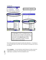
Coupling
: Select AC, DC, IEPE, 200 V MIc.
Or 0V Mic.
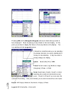
Window
: Select Rectangle, Hanning, or
Flattop.
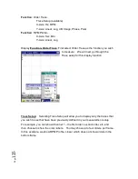
Channel ID
: Enter a value between 0 and
999.
Direction
: You can select one of the
directions from a pull-down menu.
+X, -X, +Y, -Y, +Z, -Z, +R, -R, +T, -T, +P.
Summary of Contents for Fieldpaq
Page 5: ...Page 4 ...
Page 54: ...Page 53 Orbit x y ...
Page 61: ...Page 60 ...
Page 104: ...Page 103 Power Spectrum Time Waveform Bearing Spectrum ...
Page 199: ...Page 198 ...
Page 200: ...Page 199 DVF specifications Maximum frequency band Maximum resolution Maximum file size ...
Page 204: ...Page 203 Done ...
Page 206: ...Page 205 5 Start the Data Explorer Program 6 Select File Import ...
Page 215: ...Page 214 ...
Page 222: ...6 ...


