P
ag
e
26
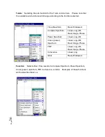
Note - The external channel is TTL signal only, so you will not have to setup other
parameters for this channel. However, if you select one of the analog channels,
i.e., Ch 1 – Ch 4, then you must set up Level, Slope and Delay %.
Level
: Select 0%, 10%, 25%, 40% or 55% trigger level.
Slope
: Select either positive or negative slope.
Delay %
: This is an input screen where you can enter an integer for a delay %
between –99 to +99.
(Note: input the “minus” sign by pressing “0” at the
beginning.)
Tacho
:
Pulses/ Rev, Hold Off Time, Show RPM
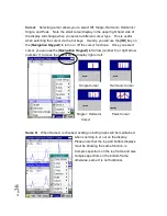
Pulses/Revolution
: Via the [
Navigation
Keypad
], press [
OK
]. You will see an input
panel to enter the number of pulses per
revolution.
If the rotation speed needs to be measured,
the program will use the above triggering
signal for calculating the RPM value.
To display the RPM, press the function key to
[
Show RPM
] and observe the displayed rpm.
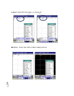
Local Soft Key Menu: Return, Show RPM,
Return
: Selecting the Return function to save the change and returns you to the
Setup menu. Selecting return again returns you to the live display.
Show RPM
: To show the rpm value, press the function key [
Show RPM
]. Once
activated, the RPM value will be displayed in the “Show RPM” column. This is to
aid in tacho setup.
Summary of Contents for Fieldpaq
Page 5: ...Page 4 ...
Page 54: ...Page 53 Orbit x y ...
Page 61: ...Page 60 ...
Page 104: ...Page 103 Power Spectrum Time Waveform Bearing Spectrum ...
Page 199: ...Page 198 ...
Page 200: ...Page 199 DVF specifications Maximum frequency band Maximum resolution Maximum file size ...
Page 204: ...Page 203 Done ...
Page 206: ...Page 205 5 Start the Data Explorer Program 6 Select File Import ...
Page 215: ...Page 214 ...
Page 222: ...6 ...


