P
ag
e
29
Channel Setup
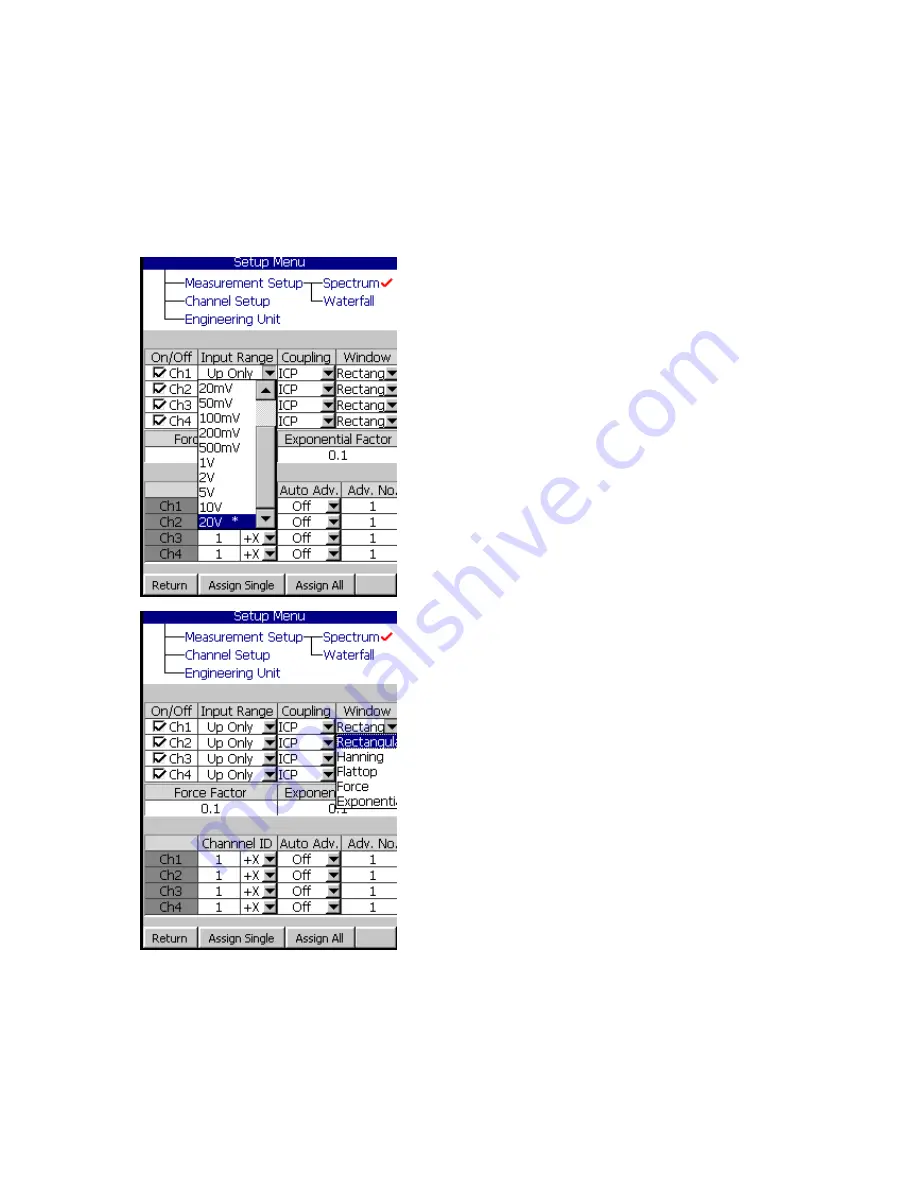
The Channel setup is so that you can define each channel according to what you
are measuring. You can turn each channel on/off, select the input range,
coupling, window, and other parameters for making a good measurement.
Channel setup applies to both Spectrum and Waterfall measurements.
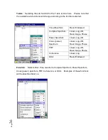
ON/ OFF
: Turns on/off each channel
Input Range
: Select Auto, Up Only, 10 mV,
20 mV, 20 mV, 50 mV, 100 mV, 200 mV, 500
mV, 1V, 2V, 5V, 10V, or 20V. This should
match the output of the device that you are
connecting to. Up only is typically used with
modal Fieldpaq testing where the range will
increase “up” as required to locate the correct
input range. Auto will automatically collapse
the input range around the center. Use this if
you are unsure of the correct input range.
Coupling
: Select AC, DC, IEPE, 200V Mic. or
0V Mic.
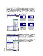
Window
: Select Rectangle, Hanning,
Flattop, Force, Exponential.
Force Factor
: With the [
Navigation
Keypad
] enter the desired force input box
and then press [
OK
]. The width of the force
window in this case is 0.1 or 10%.
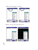
Exponential Factor
: With the [
Navigation
Keypad
] enter the desired value and then
press [
OK
]. The attenuation rate of the
exponential window in this example is equal to 0.1 or 10% at the end of the time
block.
Summary of Contents for Fieldpaq
Page 5: ...Page 4 ...
Page 54: ...Page 53 Orbit x y ...
Page 61: ...Page 60 ...
Page 104: ...Page 103 Power Spectrum Time Waveform Bearing Spectrum ...
Page 199: ...Page 198 ...
Page 200: ...Page 199 DVF specifications Maximum frequency band Maximum resolution Maximum file size ...
Page 204: ...Page 203 Done ...
Page 206: ...Page 205 5 Start the Data Explorer Program 6 Select File Import ...
Page 215: ...Page 214 ...
Page 222: ...6 ...


