n
CONNECTOR IDENTIFICATION
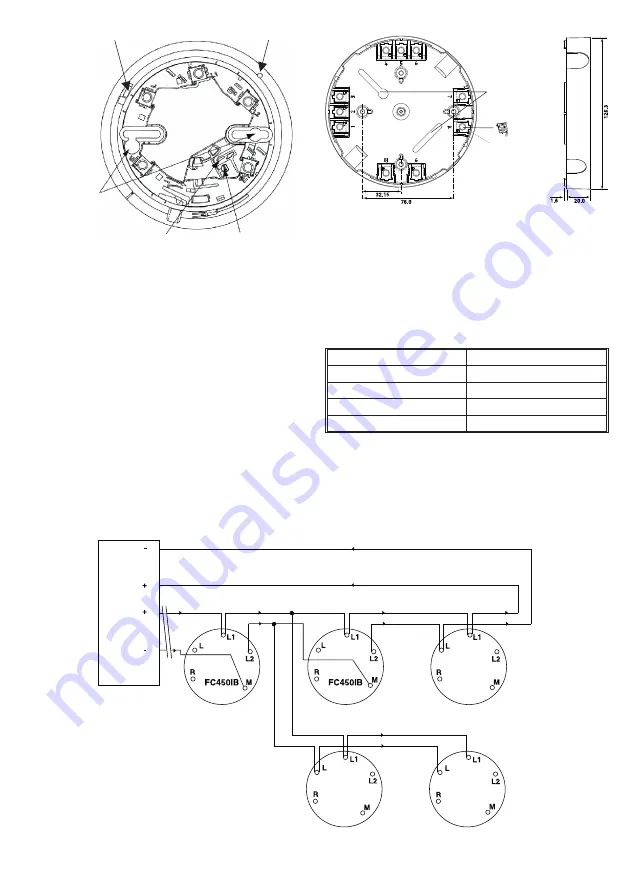
The FC450IB Isolator Base has five terminals:
R
Remote LED connector
L
Not connected
L1
+ve IN/OUT
L2
-ve OUT
M
-ve IN
n
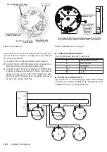
FITTING OF LOCKING DEVICE
Figs. 2 and 6 refer. To fit the locking key, break it off from the sprue
connecting it to the body moulding. Fit the locking device in the
orientation shown in Fig. 6 and push firmly in.
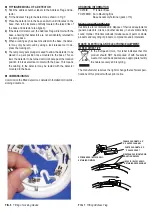
other end of the loop or any base along the loop to verify the wir-
ing up to that point. If there is no voltage out at any measured
point, this may be due to:
1)
Loop Open Circuit - wiring incomplete to part of the loop.
2)
Incorrect Polarity -FC450IB Isolator bases will appear as a
short circuit if they are wired with incorrect polarity.
3)
Loop Short Circuit - If this occurs between two FC450IB Isola-
tor bases, it will isolate that section of the line, which will then
appear as an open circuit. If this occurs between the supply
and the first FC450IB Isolator Base, the supply output will go
low due to the internal current limit.
APERTURA LED
LED APERTURE
TAPPO APERTURA LED
LED APERTURE PLUG
DISPOSITIVO DI BLOCCAGGIO
LOCKING DEVICE
FORI POSIZIONAMENTO VITI
SCREW LOCATING HOLES
SEDE DISPOSITIVO DI BLOCCAGGIO
LOCKING DEVICE SLOT
FIG. 3
Part identification
APERTURE DI FISSAGGIO
MOUNTING SLOTS
MORSETTO ACCESSORIO
PER LA BASE (BATs)
(di fabbrica, inserito solo
in una posizione)
BASE ACCESSORY
TERMINAL (BATs)
(factory fitted in
one position only)
NOTA: ULTERIORI MORSETTI POSSONO ESSERE ORDINATI IN BASE ALLE NECESSITÀ
NOTE: EXTRA BATs MAY BE ORDERED TO PROVIDE ADDITIONAL CABLE TERMINALS
FIG. 4
FC450EMB Euro mounting box
5B
5B
5B
FC
L1
L1
L1
L1
RIGHT
LEFT
FIG. 5
Simplified Circuit Diagram


