30
Multifunction Control Panel
Test Vibrat 018
DDIIZZZZ
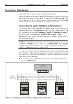
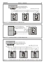
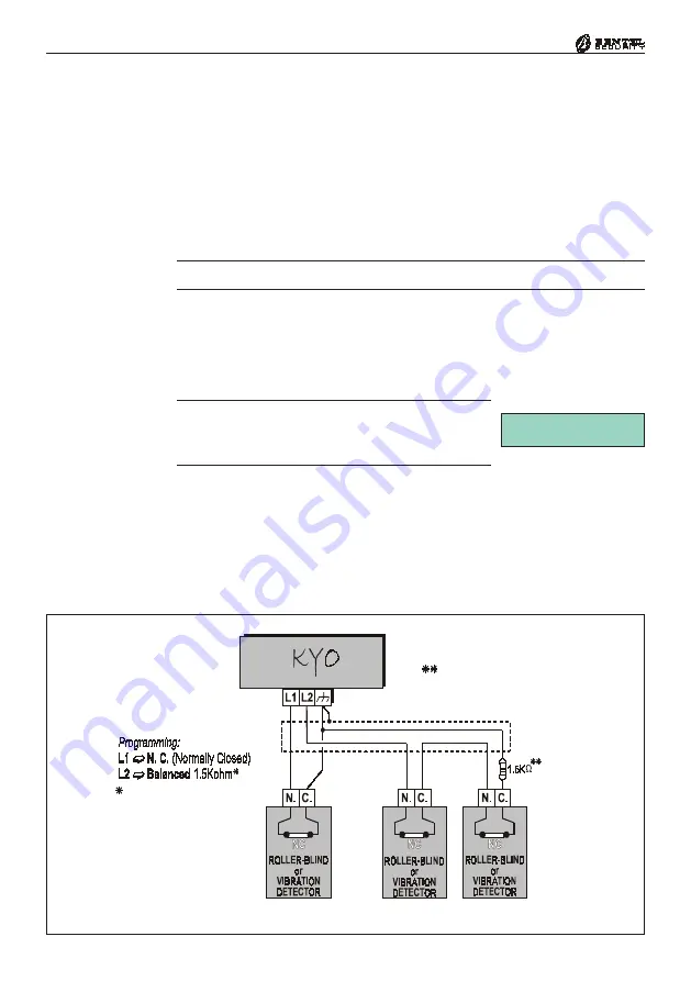
Figure 2.11 - Connecting Roller blind and Vibration detectors to a N.C. and a Balanced Line
Connecting Roller-Blind and Vibration Detectors
Zones 1 through 6 of the KYO8 and KYO32 Models
, and all zones of the KYO4
(zones 1 through 2 for Kyo16D)
support Roller-blind and Vibration detectors.
The zones must be programmed respectively with
either the
Vibration
or
Roller-blind
attribute
(refer to the
‘PROGRAMMING FROM PC’
section in
this Manual), and can be set up as Normally Closed (
N.C.
) or Balanced 1.5 K
Ω
(
BAL
). The wiring diagram in Figure 2.11 shows a typical connection. The 1.5.
K
Ω
(600ohm for Kyo16D)
Balance Resistor must be connected to the last de-
vice, as shown in Figure 2.11.
The 1.5 K
Ω
Ω
Ω
Ω
Ω
Balance Resistors are not supplied.
If the system has an LCD Keypad, it will be possible to Test the sensitivity of
the ‘
Vibration
’ zones. The system must be put in SERVICE MODE, by
leaving a Digital Key in a Reader, or by inserting the INHIBIT ALARMS
Jumper [
8
] (the zones must be tested SEPARATELY). The display will show
the Test message and the ‘Shock’ value (0 through 20).
IMPORTANT -
For the most reliable results, the ‘Vi-
bration’ attribute must be disabled on all zones except
the one being tested.
Summary of Contents for KYO 32 M
Page 1: ...0 1 7 167 7 21 0 18 ...
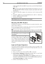
Page 10: ...10 Multifunction Control Panel The NC2 TAST LED Keypad Figure 1 3 The NC2 TAST LED Keypad D D ...
Page 71: ...71 Section 3 Programming from PC 5 11 6 0 1 2 3 1 4 3 3 5 2 3 0 1 2 3 ...
Page 88: ...ISTISBLEUNKYO 2 6 160108 P70 17 6 85 7 6 U O 01 02 5HF FOLQ LQ RU WLRQ ...


