33
Section 2 - Installation
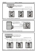
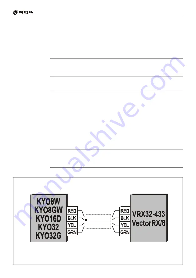
Figure 2.15 - Connecting a VRX32-433 or Vector/RX8 Receiver
Connecting the Telephone Line
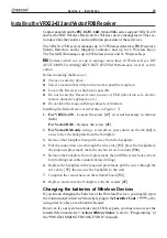
If Telephone Dialler facility is used, the Telephone line must be connected to
terminals [
LE
]. In this way, the Control panel will be the first device on the
telephone line. If the Control panel is sharing the line with another device, the
latter must be connected to terminals [
LI
] (see Figure 2.14), thus allowing the
Control panel to take priority in the event of an Alarm.
G
G
G
G
G
- Terminal [
-
-
-
-
-
] must be connected to the Mains Earth in order to protect
the PCB against line surges.
G
G
G
G
G
- Ensure that the Mains Earth line is intact and operating properly before
connecting the telephone line.
If the Control panel is not connected to the telephone line, the
Disable Tel-
ephone line check
option must be activated, otherwise, the Telephone Line
Trouble event will be signalled continuously (refer to the ‘Options Page’ in the
‘PROGRAMMING FROM PC’ section).
VRX32-433 and Vector/RX8 Receiver
Control panels with K8W, K8GW, K16D, K32 and K32G boards support
VRX32-433 and Vector/RX8 Wireless Receivers (accessory items). Connect
the Control panel terminals — [
GRN
], [
YEL
], [
BLK
] and [
RED
] to the re-
spective terminals on the Receiver, as shown in Fig. 2.15.
Use Shielded cable only. One end of the shield must be connected to the
[BLK] terminal on the Control panel. Do not exceed 50 meters of cable
length.
Summary of Contents for KYO 32 M
Page 1: ...0 1 7 167 7 21 0 18 ...
Page 10: ...10 Multifunction Control Panel The NC2 TAST LED Keypad Figure 1 3 The NC2 TAST LED Keypad D D ...
Page 71: ...71 Section 3 Programming from PC 5 11 6 0 1 2 3 1 4 3 3 5 2 3 0 1 2 3 ...
Page 88: ...ISTISBLEUNKYO 2 6 160108 P70 17 6 85 7 6 U O 01 02 5HF FOLQ LQ RU WLRQ ...


