15
Bentone
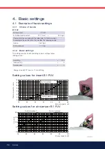
4.2 Suction plate
In the case of higher power, as well as with boilers featuring overpressure
in the combustion chamber, it is possible to achieve higher fan pressure by
altering the position of the suction plate, see illustration. The plate is located
beneath the outer half of the fan housing, see illustration, Cleaning the fan
wheel.
-
Position 1 is normally used for nozzles up to 0.60 gph and position 4
for larger nozzles. Position 2 and 3 are intermediate positions. Positi-
on 5 and higher does not give more pressure and they are not used.
-
Check that the plate is placed in the correct position. Otherwise the
aircannot be adjusted to the correct value.
4.2.1 Insert control
The burner is equipped with a lever that changes the position of the brake
plate in the burner tube. This is used to set the correct pressure drop across
the combustion assembly, thereby obtaining good combustion without
pulsation.
The setting to be used depends on, among other things, the output settings
and overpressure in the boiler
Setting the brake plate
• Small column: turn the screw left
• Large column: turn the screw right
Setting the brake plate position af
fects airflow. Therefore, it is always
necessary to fine-tune airflow using the burner’s airflow regulator.
4.2.2 Air intake adjustment
Setting the air intake is very important to achieve good combustion with
neither too much nor too little air. To adjust the combustion airflow, turn the
airflow knob lever. The extent to which the airflow lever must be open is
determined by the heat output and overpressure in the boiler as well as other
settings on the burner such as the position of the brake plate.
4.2.3 Setting the air quantity
Turn the air intake clockwise to increase airflow and anticlockwise to
decrease airflow.
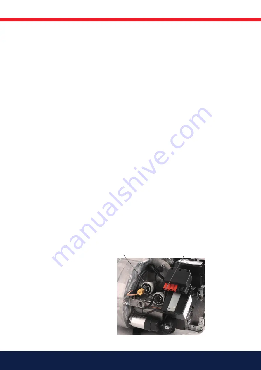
Insert control
Air control
Summary of Contents for B 1 FUV 63-16
Page 31: ...171 905 28 ...
Page 34: ......
Page 35: ......
Page 36: ...Enertech AB P O Box 309 SE 341 26 Ljungby www bentone se www bentone com ...


