background image

13


Bentone 

!

If any electrical connection is used other than that recommended by Enertech, there may be a risk of 

damage to property and personal injury.

3.2  Delivery inspection

Make sure everything is delivered and the goods have not been damaged 

during transit. If something is wrong with a delivery, report it to the supplier. 

Transport damage must be reported to the shipping company.

3.3  Preparing for installation

Check that the burner’s dimensions and capacity range are suitable for the 

relevant boiler. The power data on the rating plate refers to the burner’s 

minimum and maximum power.

3.4  Oil distribution

In order to achieve good reliability, it is important that the oil distribution 

system is designed correctly.

Take the following into account:


-

Selection of pipe diameter, pipe length and height difference; see 
Pump instruction.


-

Pipelines are to be laid with the fewest possible number of glands. 


-

The pipes are to be laid so that the oil supply hoses are not subjected 
to tensile stresses or become excessively bent when the burner is 
swung out or removed for servicing.


-

The oil filter should be installed so that the filter cartridge can easily be 
replaced or cleaned. 


-

Parts in contact with oil must be selected in materials that are capable 
of withstanding the medium’s physical properties.


-

When installing oil hoses, check that the inlet and return hoses are 
fitted to the appropriate connection on the oil pump. The hoses must 
be located so that they do not bend or become subject to tensile 
load. 


-

Bleed the oil system. The oil pump/oil preheater may be damaged if 
run dry. The vacuum in the suction line should not fall below 0.3 bar 
during start-up.

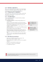
!

Be sure to fill the 
burner oil system 
before starting it for 
the first time.

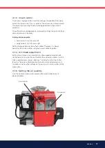
3.5  Electrical connection

•  Before work on the electrical connection, the current must be 

disconnected so that the installation is isolated.

•  Electrical connection must be done in accordance with the applicable 

regulations.

•  Burners must be connected to an all-pole switch.

•  Connection must conform to the wiring diagram.

•  Use appropriately sized fuses.

!

The oil filter must 
be installed before 
the burner’s oil 
pump

Summary of Contents for BENTOFLEX ST 146 B30A

Page 1: ...Providing sustainable energy solutions worldwide 17810019 1 2019 09 20 Installation and maintenance instruction BENTOFLEX ST 146 B30A...

Page 2: ...le Beispiel exempel Manuels dans d autres langues www bentone com download ou scannez le code QR Saisir le num ro d article du br leur sur votre plaque signal tique consultez l illustration et s lecti...

Page 3: ...15 5 Burner servicing ____________________________________ 18 5 1 Servicing _______________________________________ 18 5 2 Servicing the combustion device ___________________ 18 5 3 Replacing the oil...

Page 4: ...elative humidity no condensation Temperature 20 to 60 C Check that the burner is compatible with the boiler s output range The label information on the rating plate refers to the burner s minimum and...

Page 5: ...tch this must be equipped with a hatch opening switch connected to the burner s safety system When in operation the burner s noise level can exceed 85 dBA Use hearing protection The burner must not be...

Page 6: ...h Change cleaning Brake plate 1 Year Change cleaning 3000h Change cleaning Motor 1 year 3000 hrs Cuppling chaft 1 year control change 3000h control change Fan wheel 1 Year Change when dirty unbalance...

Page 7: ...l B10 heating oil biofuel blend as defined in DIN V51603 6 and is used for Water heating generators Hot air generators these require LMO 24 255 C2E 2 1 Dimensions ST 146 Min recommended distance to fl...

Page 8: ...9 5 d1 d 2 d 3 Combustion device d1 d2 d3 ST 146 110 M10 140 170 2 3 Burner installation 2 3 1 Hole patten Make sure the hole pattern on the boiler is designed for burner flange Length of blast tube P...

Page 9: ...ete burner Sound ST 146 B30A 125W 0 95A 230V 50 60Hz 4 F 230V 0 95A 50Hz 79 dBA 0 5 dBA ST 146 B30AV 125W 0 95A 230V 50 60Hz 4 F 230V 1 15A 50Hz 79 dBA 0 5 dBA 2 5 1 Electric Specification Burner corr...

Page 10: ...0 39 3 42 40 0 85 2 83 33 3 00 36 3 16 37 3 32 39 3 47 41 3 61 43 3 74 44 3 87 46 1 00 3 33 39 3 53 42 3 72 44 3 90 46 4 08 48 4 24 50 4 40 52 4 56 54 1 10 3 66 43 3 88 46 4 09 48 4 29 51 4 48 53 4 67...

Page 11: ...tion cables 5 Nozzle assembly 6 Nozzle 7 Brake plate 8 Blast tube 9 Ignition electrodes 10 Connecting pipe 11 Air damper 12 Solenoid valve 13 Pump 14 Drive coupling 15 Indication air damper 16 Fan whe...

Page 12: ...ot pinched or otherwise damaged during installation or servicing 3 1 1 Installation and Maintenance Manual The maintenance instructions supplied with the burner must be kept at an easily accessible lo...

Page 13: ...ected to tensile stresses or become excessively bent when the burner is swung out or removed for servicing The oil filter should be installed so that the filter cartridge can easily be replaced or cle...

Page 14: ...of the oil filter 3 For single pipe systems the return plug must be removed refer to Pump instructions 4 When installing oil hoses check that the supply and return hoses are fitted to the appropriate...

Page 15: ...146 B30A Burner output 70 kW Output calculation due to preheater for nozzle choice according to the table refer to Technical data Estimated nozzle output 70 x 1 06 74 2 kW 74 2 11 86 6 25 kg h Choice...

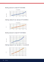
Page 16: ...r ST 146 B30A 0 10 20 30 40 50 70 90 110 130 150 ST146 B30A 0 10 20 30 40 50 70 90 110 130 150 ST146 B30A Air Insert scale Setting values for insert ST 146 B30AV Setting values for air damper ST 146 B...

Page 17: ...position affects airflow Therefore it is always necessary to fine tune airflow using the burner s airflow regulator 4 1 4 Air intake adjustment Setting the air intake is very important to achieve goo...

Page 18: ...off mains power and disconnect the Europlug from the burner 2 Remove the burner from the boiler by loosening the screw A 3 Loosen the housing screw B and remove the front cover C 4 Visually inspect t...

Page 19: ...pump 5 Disconnect the solenoid valve cable from the pump 6 Disconnect the connection tube D from the pump 7 Loosen the screws E and pull out the oil pump 8 Install the new oil pump on the burner Tigh...

Page 20: ...eel 9 Fit the fan wheel to the motor tighten the locking screw The fan wheel must be fitted with a little play between the motor and the fan wheel Make sure that there are no scratching noises Refit t...

Page 21: ...witch on mains power start the burner and check the combustion 5 6 Replacing the entire electrical package 1 Switch off mains power and disconnect the Europlug from the burner 2 Remove the burner from...

Page 22: ...emove the burner control and loosen the two bottom screws in the relay socket 4 The Europlug plate is firmly attached under the relay socket 5 Remove the cable of the component to be replaced 6 Connec...

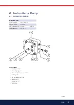
Page 23: ...nge 1 3 12 0 mm2 s Pressure range 7 15 bar Rated voltage of coil 220 240V 50 60 Hz Oil temperature max 60 C Components 1 Nozzle port G1 8 2 Pressure gauge port 3 Pressure adjustment 4mm allen key 4 Ca...

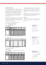
Page 24: ...00 4 00 6 00 9 50 H m 4 4 4 4 4 6 4 6 4 6 8 4 6 8 4 6 8 10 A2L pumps sum up the 2 nozzles A2L Pumpen Summe der zwei D sen pompeA2L sommedes2gicleurs PerlepompeA2Laggiungeren 2ugelli Two pipe system 0...

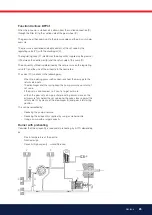
Page 25: ...line The valve P1 functions in the following way When the opening pressure has been reached the passage to the return side opens The diaphragm and the spring keep the pump pressure constant at set val...

Page 26: ...plug in the cover by means of a 4 mm allen key and withdraw the cartridge filter If necessary put a screwdriver between the cartridge filter and the plug and turn the cartridge filter carefully until...

Page 27: ...on and fuses in accordance with local regulations If there is no plug in contact X2 on the boiler connect to the contact enclosed In case the twin thermostat is in series on incoming phase L1 a loop b...

Page 28: ...nical data oil burner control 3 a b The safety time expires If no flame is established before this time limit the control cuts out If for some reasons the flame disappears after this time limit the bu...

Page 29: ...sed the problem by pressing and holding the reset button for 3 seconds The number of flashes below is repeated with a pause in between 2 flashes No flame signal when safety time expires 4 flashes Fals...

Page 30: ...nt light Check high voltage wiring and ignition electrodes Check preheater function Symptom Burner does not start Burner pre ventilates Burner stops Causes Fuse blown Boiler thermostat has not reset P...

Page 31: ...ght Adjust the burner Check preheater function Adjust the preheater s set operating temperature Ensure that the new oil s physical parame ters are within the limits for which the burner is designed If...

Page 32: ...171 905 28...

Page 33: ...Address Test performed by Postal address Company name Tel no Boiler Type Make Power kW Bentone Burner Type Model Serial no Fuel Step 1 Step 2 Step 3 Draught in fireplace Fan Press mbar Filter smoke nu...

Page 34: ...perature If the burner will not start Press the reset button on the relay Check that the thermostats are correctly adjusted Don t forget the room thermostat check that any fusesare intact and main swi...

Page 35: ......

Page 36: ...Enertech AB P O Box 309 SE 341 26 Ljungby www bentone se www bentone com...

Reviews: