background image

27


Bentone  BF1  

General

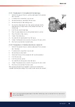
6.1.3  Filter replacement

Cut off the power and shut off the oil.

Remove the pump cover with the aid of a 4 mm Allen key. If necessary a 

screwdriver may be used between the cover and the housing to carefully 

pry the cover loose. Replace the old i lter by a new one. Replace the cover, 

tighten lightly.

Do not forget to replace the gasket.

Open the oil supply and switch on the power.

3

2

4

7

8

5

1

9

6

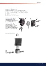
6.1.4  One-pipe system 

Conversion to one-pipe system

Remove the return plug (8), plug the return 

line (9) with the metal plug (7) G 1/4”. 

6.1.5  Two-pipe system

Conversion to two-pipe system

Remove the metal plug (7) G ¼”, i t the 

return plug (8) in the return line (9).

Return plug are not included in products 

with one-pipe system, separately sold.

6.1.6  Solenoid valve

Summary of Contents for BF1 RME

Page 1: ...Providing sustainable energy solutions worldwide 178 116 35 5 2017 12 05 Installation and maintenance instruction BF1 RME...

Page 2: ......

Page 3: ..._________________________17 5 1 Warning ________________________________________________________________17 5 1 1 Service position___________________________________________17 5 1 1 1 Service position...

Page 4: ...aller to ensure that no electrical cables or fuel gas pipes are trapped or damaged during installation or service maintenance Burners which are fuelled by FAME RME are and must be equipped with parts...

Page 5: ...s too large The temperature of the lue gases should exceed 60 C measured 0 5 metres from the chimney top Measures to raise the temperature Insulate the chimney in cold attics Install a tube in the chi...

Page 6: ...0 6 0 8 0 10 0 12 0 14 0 16 0 18 0 20 0 22 0 15 20 25 30 35 40 45 50 55 Burner output kW Scale Air settings Nozzle assembly Scale value applies to 0 mbar furnace pressure 1 1 Model BF1 FUV 63 16 Leng...

Page 7: ...W Boiler overpressure mbar 0 5 0 0 0 5 1 0 1 5 2 0 2 5 3 0 3 5 4 0 40 45 50 55 60 65 70 75 80 85 90 95 100 Length of blast tube Protrusion from lange measurement B Flange 1 2 3 4 117 82 95 103 102 147...

Page 8: ...ue applies to 0 mbar furnace pressure Flange 1 Flange 2 Flange 3 Flange 4 12 89 5 136 150 12 10 3 25 130 150 89 7 125 90 4 1 0 125 150 90 5 10 3 89 172 B 190 226 2 TECHNICAL DATA 2 1 Dimensions BF1 2...

Page 9: ...0 39 3 42 40 0 85 2 83 33 3 00 36 3 16 37 3 32 39 3 47 41 3 61 43 3 74 44 3 87 46 1 00 3 33 39 3 53 42 3 72 44 3 90 46 4 08 48 4 24 50 4 40 52 4 56 54 1 10 3 66 43 3 88 46 4 09 48 4 29 51 4 48 53 4 67...

Page 10: ...screw 6 Oil burner control 7 Electrical contact X3 refer to wiring diagram 8 Motor 9 Capacitor 10 Preheater where itted 11 Ignition electrode 12 Ignition cable 13 Photoresistor 14 Inspection glass 15...

Page 11: ...11 Bentone BF1 General 2 11 12 1 10 5 15 24 22 21 23 13 3 17 14 19 20...

Page 12: ...e ilter cartridge can easily be replaced 3 4 Electrical connection Before electrical installation is begun electricity must be switched off at the main switch If the boiler has a 7 pole or a 4 pole Eu...

Page 13: ...pply line If an air separator is itted the oil ilter should be installed before the air ilter to increase the life span of the ilter 3 For one pipe systems the return plug must be removed Refer to Pum...

Page 14: ...F1 KV 76 26 Burner output 30 kW Because of preheater output is adjusted upward for choice of nozzle according to table Refer to Technical data 2 6 Estimated nozzle output 30 x 1 06 31 8 kW 31 8 11 86...

Page 15: ...ulator with an Allen key How far open the air regulator must be is determined by output furnace pressure and other burner settings such as blast tube position 4 1 5 Method of adjusting air quantity Se...

Page 16: ...r intake and the two screws which retain the pump Then rotate the air intake to the desired position and tighten the screws The position of the air intake affects the airlow through the burner somewha...

Page 17: ...from the burner front piece 3 Remove the fan housing from the burner front piece and pull it backwards until the combustion assembly is free of the burner front piece 4 Suspend the fan housing by the...

Page 18: ...n the illustration 5 1 2 Combustion assembly service 1 Switch off the power at the main switch and disconnect the Eurostecker from the burner 2 If so desired service position 1 may be used 3 Carry out...

Page 19: ...age 4 Disconnect the preheater cable from the preheater 5 Screw off the nozzle 6 Undo the nut that connects the oil pipe to the preheater 7 Install the new preheater Check the condition of the O ring...

Page 20: ...rrent and disconnect the Euro plug from the burner 2 Disconnect the electrical plug from the oil valve 1 3 Detach the oil hoses from the pump 4 Detach the solenoid valve housing from the valve 2 Remov...

Page 21: ...Install the fan wheel on the new motor tighten the locking screw The fan wheel must be installed in the bottom position toward the motor shaft Install the drive coupling end 10 Align and it the motor...

Page 22: ...when installing the inlet cone install it in the same position it had at removal 11 Fit the O ring in the groove between the fan housing and inlet cone Ensure that it is properly located in the groove...

Page 23: ...the fan wheel Undo and if necessary remove the fan wheel for more thorough cleaning of the fan and fan housing 10 Install the fan wheel tighten the retaining screw The fan wheel must be installed in...

Page 24: ...an wheel must be installed in the bottom position toward the motor shaft Install the drive coupling end 10 Align and it the motor lange to the fan housing Pay attention to the drive coupling so that i...

Page 25: ...Screw the electrical box in place 9 Connect the motor wiring 10 Assemble the fan housing and burner front piece 11 Connect the Eurostecker and switch on the power at the main switch 12 Start the burne...

Page 26: ...ty range 2 0 75 0 mm2 s cSt Pressure range 7 14 bar Oil temperature max 60 C 6 1 2 Components 1 Nozzle connection G 1 8 2 Vacuum manometer connection G 1 8 3 Manometer connection G 1 8 4 Filter 5 Suct...

Page 27: ...e Replace the cover tighten lightly Do not forget to replace the gasket Open the oil supply and switch on the power 3 2 4 7 8 5 1 9 6 6 1 4 One pipe system Conversion to one pipe system Remove the ret...

Page 28: ...a one pipe installation back to the suction connection in the gear wheel pump Two pipe system When the solenoid valve is not activated the return plug channel between the pressure side and the return...

Page 29: ...oil low are adapted to prevent turbulent lows from occurring Turbulent lows can result in pressure losses and noise in the pipework A typical pipe system usually comprises pipe runs with 4 bends a non...

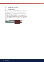
Page 30: ...ter thermostat closes and the burner receives the start signal During operations the PTC element compensates its output so that the temperature does not become too high If the oil temperature is low a...

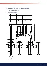
Page 31: ...31 Bentone BF1 General Alt 1 According to DIN 4791 Alt 2 Alt 3 Alt 4 8 ELECTRICAL EQUIPMENT LMO1 2 4 8 1 Wiring diagram...

Page 32: ...the pre heating period begins This continues until the operating temperature is reached and the preheater thermostat closes The burner motor starts ignition sparks initiated and pre ventilation contin...

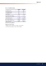
Page 33: ...connection after release 1 s 1 s Reaction time lame extinction 1 s 1 s Ambient temperature 5 60 C 5 60 C Min current with lame 45 A 45 A Max current when dark start 5 5 A 5 5 A Ingress Protection IP 4...

Page 34: ...what has caused the problem by pressing and holding the reset button for 3 seconds The number of lashes below is repeated with a pause in between 2 lashes No lame signal when safety time expires 4 las...

Page 35: ...tive oil burner control or lame monitor No oil supply Too great a pressure drop at brake plate Too strong draught prevents lame forming No spark Check and replace fuse as necessary Investigate cause o...

Page 36: ...10 DECLARATION OF CONFORMITY...

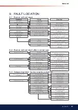
Page 37: ...start Press the reset button on the relay Check that the thermostats are correctly adjusted Don t forget the room thermostat check that any fusesare intact and main switch is on If the burner starts b...

Page 38: ......

Page 39: ......

Page 40: ...Enertech AB P O Box 309 SE 341 26 Ljungby www bentone se www bentone com...

Reviews: