16
Bentone BG550/650
General
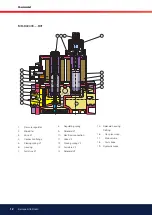
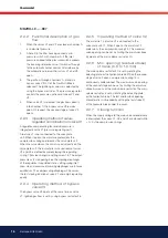
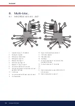
2.2.2 Functional description of gas
flow
1.
When the valves V1 and V2 are closed, chamber A
is under inlet pressure.
2.
A hole D in the ilter housing connects min.
pressure switch with chamber A. If the inlet
pressure applied to the pressure switch exceeds
the incoming reference value, it switches through
to the automatic burner control. After release by
the automatic burner control, valves V1 and V3
open.
3.
The gas low through chambers A, B and via
bypass valve V3 in C of the GasMulti-Bloc is
released. The ignition gas volume is adjusted by
using the bypass restrictor. The pressure regulator
controls the pressure upstream of valves V2 and
V3.
4.
When valve V2 is released, the gas lows directly
into chamber C, the bypass valve V3 remains
open. On request, the second stage of valve V2
opens.
2.2.3
Operating method of valve-
regulator combination on valve V1
A regulator, compensating for residual pressure is
integrated in valve V1 (pressure regulating part).
Armature V1 is not connected to the valve plate
unit. When it opens, the armature pretensions the
compression spring and releases the valve plate unit.
When the valve closes, the armature acts directly on the
valve plate unit. The output pressure upstream of valves
V2 and V3 is deined by pretensioning the regulating
spring 7 (tension spring) via setting screw 18. The output
pressure acts via opening E on the working diaphragm
of the regulator. In regulated state, setting spring inlet
pressure and pressure of working diaphragm are in force
equilibrium. The compensating diaphragm 23 ensures
the fast closing function of valve V1 and a high regulating
quality.
2.2.4 Operating method of bypass
valve V3
The bypass valve V3 opens at the same time as valve
V1. Ignition gas low is set by using bypass restrictor 28.
2.2.5 Operating method of valve V2
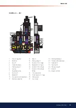
The armature 14 of valve V2 is connected to the
valve plate unit 12. When it opens, the armature 14
pretensions the compression spring 13. The maximum
valve opening can be set by limiting the armature stroke
by means of the main volume restrictor 20.
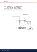
2.2.6 Min. opening (residual stroke)
of Valve (0.5 to 1.0 mm)
The main volume restrictor 20 is set by rotating the
adjusting plate or the hydraulic brake. When the second
stage of valve 2 opens, compression spring 13 is
continuously pretensioned. The maximum valve opening
of the second stage can be set by limiting the armature
stroke by means of the main volume restrictor. The main
volume restrictor is set by rotating the adjusting plate
or the hydraulic brake. The fast and/or slowl opening
characteristic is inluenced by setting the fast stroke 21
at the hydraulic brake under the cover.
2.2.7 Closing function
When the supply voltage to the main valve solenoid coils
is interrupted, the valves V1, V3 and V2 are closed within
< 1 s by the compression springs.
MBZRD-LE......B07


