3
Bentone BG550/650
Contents
1. Technical data
_________________________________________________________________
8
1.1 Dimensions
________________________________________________________________
8
1.2
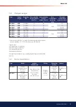
Output range
______________________________________________________________
9
1.3
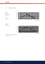
Working ield
____________________________________________________________
10
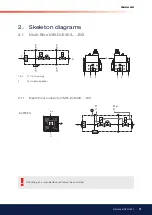
2. Skeleton diagrams
________________________________________________________
11
2.1
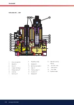
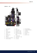
Multi-Bloc MB-DLE403.....B01
___________________________________
11
2.2
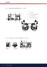
Multi-bloc MBZRD-LE......B07
____________________________________
14
2.3
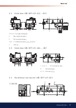
Multi-bloc MB-VEF 407-412.....B01
____________________________
17
2.5
Multi-bloc MB-VEF 415-420.....B01
____________________________
17
2.4
Electritrical connection MB-VEF 407-420
_____________________
17
3. Description
_____________________________________________________________________
18
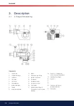
3.1 2-Stage/Modulating
__________________________________________________
18
4. Mounting of the burner
_________________________________________________
19
4.1
Inspection of gas assembly
________________________________________
19
4.2
Adjustment of the position of the shrouded disc in the blast
tube
_________________________________________________________________________
20
4.3
Wiring diagram LFL1... (BG550/BG650) 2-Steg
____________
21
4.4
Wiring diagram LFL1... (BG550/BG650) Modulating
_____
22
4.5
List of components LFL1... (BG550/BG650)
________________
23
4.6
Funktion LFL1...
________________________________________________________
24
4.7
Control programme under fault conditions and lockout indica-
tion LFL1....
______________________________________________________________
25
5. Measures and checks
before start-up
______________________________________________________________
26
5.1
2-Stage or modulating burners
___________________________________
26
6. Determination of gas volume for the installation
_______
28
6.1
Example how to calculate the gas volume (natural gas)
_
28
7. Gas pressure regulator Type FRS
_______________________________
29
8. Multi-bloc,
_____________________________________________________________________
30
8.1
MB-ZRDLE 405-415....B07
________________________________________
30
8.2
Mounting K01/1
________________________________________________________
31
8.3
Flow adjustment 2-stage design
_________________________________
32
8.4
Adjustment of of main valve damper
___________________________
32
8.5
MULTI-BLOC, MB-VEF 412-415.... B01
______________________
33
8.6
MULTI-BLOC, MB-VEF 420-425.... B01
______________________
34
8.7
Technical data
___________________________________________________________
35
8.8
Mounting instruction - impulse lines P
L
, P
F
och P
Br
__________________
35
8.9
Adjustment possibilities
_____________________________________________
35
8.10 MULTI-BLOC, MB-DLE 403.... B01
_____________________________
36
8.11 Flow adjustment
_______________________________________________________
37
8.12 Adjustment of start gas low
_______________________________________
37
8.13 Adjustment of governor
_____________________________________________
37
9. Damper motor 2-stage
_________________________________________________
38
9.1
Air adjustment
__________________________________________________________
38
9.2
Releasing button:
______________________________________________________
38
10. Damper motor modulating
___________________________________________
39
10.1 Air adjustment
__________________________________________________________
39
10.2 Releasing button:
______________________________________________________
39
11. General Instructions
______________________________________________________
40
11.1 Adjustment of burner
_________________________________________________
40
11.2 Service
_____________________________________________________________________
40
11.3 Flame monitoring and measurement of ionisation current
41
11.4 UV-detector
______________________________________________________________
41
11.5 Adjustment of air pressure switch
_______________________________
42
11.6 Adjustment of min. gas pressure switch (option)
___________
42
11.7 Adjustment of max. gas pressure switch (option)
__________
42
12. Leakage control, Dungs VPS 504 series 2 (option)
___
43
12.1 Technical data
___________________________________________________________
43
12.2 Programme sequence
_______________________________________________
43
12.3 Program sequence schedule
______________________________________
44
12.4 Electrical connection VPS 504
___________________________________
44
13. Handing over of the installation
___________________________________
45
13.1 Fault location, functional troubles
________________________________
45
14. Fault location guide
______________________________________________________
46
15. General instructions for gasburners
___________________________
49
15.1 Installation
________________________________________________________________
49
15.2 Maintenance
_____________________________________________________________
49


