30
Bentone
172 615 57 2018-08-10
For continuous operation!
No-load voltage at ION terminal
(X10–05 terminal 2)
Approx. UMains
!
Protect the ionization probe against electric shock
hazard!
Short-circuit current
Max. AC 1 mA
Required detector current
Min. DC 4 µA, flame display approx.
30%
Possible detector current
Max. DC 16…40 µA, flame display
approx. 100%
Threshold values when flame is supervised by an ionization probe:
- Start prevention (extraneous
light)
Intensity of flame (parameter 954)
≥
18%
- Operation
Intensity of flame (parameter 954)
>24%
Technical data
5.6
Flame monitoring and ionisation
current check
The standard version of the burner is monitored according to the
ionisation principle. The ionisation current should be checked on
initial start-up and at each service visit.
The reason for low ionisation current can be leakage current, poor
connection to earth, fouling or incorrectly positioned ionisation
electrode in the combustion head. Sometimes the wrong gas-air
mixture can also cause a very poor ionisation current.
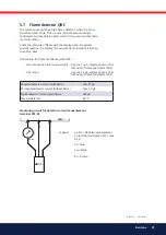
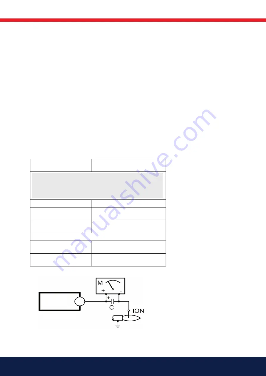
The ionisation current is measured with a microampere meter (µA)
that is connected in series with the ionisation electrode and the gas
burner control.
Connect the µA meter according to the figure. The minimum required
ionisation current is shown in the table. In practice, this current must
be significantly higher, preferably more than 10 µA. The connection of
the µA instrument is made easier by the fact that all gas burners are
equipped with a divisible ionisation cable.
LMV
X10-05,2
Summary of Contents for STG 146i/2
Page 34: ...34 Bentone 6 2 Wiring diagram...
Page 123: ......
Page 124: ...Enertech AB P O Box 309 SE 341 26 Ljungby www bentone com...


