73
Bentone
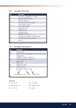
9.4.1
The parameters below may need to be set
according to the nature of the installation.
To change any of the parameters set out below, go into parameter
level and make the required adjustments.
9.4.1.1
Pressure switch-min input
236 Gas: Pressure switch-min input
0 = inactive
1 = pressure switch-min (upstream of fuel valve 1)
(Factory settings marked with bold text).
9.4.1.2
Execution valve proving
241 Gas: Execution valve proving
0 = no valve proving
1 = valve proving on startup
2 = valve proving on shutdown
3 = valve proving on startup and shutdown
(Factory settings marked with bold text).
At an input power higher than 1,200 kW, a tightness test must be
performed. At an input power lower than 1,200 kW, performing a
tightness test is optional. It is essential for all changes to take local
standards and regulations into consideration.
9.4.1.3
Active detector flame evaluation
221 Gas: Active detector flame evaluation
0 = QRB / QRC
1 = ION / QRA
(Factory settings marked with bold text).
When replacing detector flame between ionisation and UV-cell (QRA),
no change to the setting parameters is required; simply disconnect
and connect ionisation and UV-cell (QRA) respectively.
9.4.1.4
Prepurging
222 Gas: Prepurging
Index 0 = deactivated
Index 1 = activated
(
Factory settings marked with bold text).
When using valve proving and 2 fuel valves of class A, prepurging is
not required (conforming to EN 676).
If not activated, it is nevertheless performed if one or several of the
following conditions apply:
•
Alterable lockout position.
•
After an off time of >24 hours.
•
In the event of a power failure (power-on).
•
In the event of shutdown due to an interruption of gas supply
(safety shutdown).
!
Depending on the type of burner,
the automatic control unit should be
set to either “0=no valve proving” or
“1=valve proving on startup”.
Summary of Contents for STG 146i/2
Page 34: ...34 Bentone 6 2 Wiring diagram...
Page 123: ......
Page 124: ...Enertech AB P O Box 309 SE 341 26 Ljungby www bentone com...

