background image

Wireless function:  

Button 1  

Pressing button 1 will turn on engine and house batteries. 

Button 2  

Pressing button 2 will turn off engine and house batteries. 

Button 3 

When the batteries are turned on press button 3 and all of the lights will 
turn on press button 3 again and the lights will shut off. 

Button 4 

Pressing button 4 will energize the lights used for night time running and 
shut off lights not used for operating the boat at night. 

Helm Mode Button on Dash Panel:  

Pressing the mode switch will cycle thru several different modes. The first 
mode turns on all of the lights. The second mode puts the boat into night 
running mode. The third press is the Mood lighting mode. The fourth press 
will shut off all of the lights. 


Console Button at DC Panel:


Press the house or engine button to turn on or off the house or engine 
battery switch. 


https://www.boat-manuals.com/

Summary of Contents for CZONE

Page 1: ...nergize the lights used for night time running and shut off lights not used for operating the boat at night Helm Mode Button on Dash Panel Pressing the mode switch will cycle thru several different modes The first mode turns on all of the lights The second mode puts the boat into night running mode The third press is the Mood lighting mode The fourth press will shut off all of the lights Console B...

Page 2: ...ed or the button at the DC panel is pressed During the time that the battery switch is in Auto On mode the Auto On LED is illuminated Auto operation of the Battery Switch is not possible while in manual mode If auto operation is attempted the LED will flash for 3 seconds then stop Knob must be returned to Auto Off before normal auto operation can continue Auto Mode LED Indications LED OFF Battery ...

Page 3: ...d low frequency alarm Displays AC power consumption in kW calculation uses power factor for true RMS DI features Fluid level display Displays multiple tank levels and multiple fluid types Fuel Diesel and Gas Fresh water Black water Grey water Switching thresholds can be set for tank levels to raise alarms or to control an output i e a ballast pump can be automatically con trolled via the ballast w...

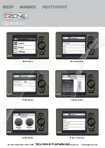
Page 4: ...or more information contact BEP ph 64 9 415 7261 email enquiries bepmarine com www bepmarine com Main Screen Monitoring Page DC Monitoring Tank Monitoring AC Monitoring Main Control Page https www boat manuals com ...

Page 5: ...Control Page Detailed Control Page Settings Menu Alarms Page Operation For more information contact BEP ph 64 9 415 7261 email enquiries bepmarine com www bepmarine com https www boat manuals com ...

Page 6: ...a numeric lists in configuration pages Off Turns circuit off decreases values in set up screens such as backlighting level ON Turns circuits on Increases values in set up screens such as backlighting level Power Key Turns display off and on Main Menu page NMEA 2000 connector Power connector Top View mounted in panel Connections For more information contact BEP ph 64 9 415 7261 email enquiries bepm...

Page 7: ...Display Interface Operation Manual Leading By Design https www boat manuals com ...

Page 8: ...f radio frequency energy which should not interfere with normal radio equipment if installed properly If interference is detected and attributed to this device you could try to Re orient or relocate the receiving antenna Separate the equipment and the receiver Isolate circuit output between the device and the radio Contact an experienced technician or dealer to help It is the owner s sole responsi...

Page 9: ... 1 Overview 5 Display Interface 6 Powering the DI 7 Screen Features 7 2 Navigation Conventions 9 Spin box Data Entry 9 3 Directory Tree 10 MONITORING 10 CONTROL 11 MODES 11 SETTINGS 12 4 Specifications 17 5 Contact Addresses 18 https www boat manuals com ...

Page 10: ...throughout your vessel is the Display Interface or DI All other interfaces are normally configured at the time of installation and re configured very occasionally in your vessel s life Once installed your DI becomes the main way you can oversee and configure the entire system But like any other interface removing the DI from the network does not cripple the network all other interfaces work with e...

Page 11: ...menu navigation sometimes used in configuration screens for quickly selecting from a large set of values OFF Decrease a value disable an interface channel ON Increase a value enable an interface channel POWER Activates Deactivates the DI NOTE F The POWER Button has no effect on the network Its only use is to activate and deactivate the DI s screen power https www boat manuals com ...

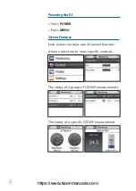
Page 12: ...ing the DI Press POWER Press MENU Screen Features Each screen contains one of several features A menu selection to more specific controls The status of a group of CZONE measurements The status of a specific CZONE measurement https www boat manuals com ...

Page 13: ...7 CZONE Display Interface Operations Manual A list of checkboxes A spin box of multiple variables The Dial is used to change values https www boat manuals com ...

Page 14: ...NU to return to the main menu Use OFF ON to decrease or increase values ENT Spin box Data Entry In some system configurations the Dial is used for spin box entry either to select an item from a long list of values or text entry If a target screen has a spinbox field rolling the Dial cycles through the values available or the alphabet of the currently active character If the currently active charac...

Page 15: ...1 Data Data all Data 1 Voltage V Current A Time Remaining A h Charge State MONITORING Tank level level L Gal capacity L Gal The Data collections appearing in this screen are configured in Settings The Monitoring section of the DI provides quick reference general and detailed views of circuit status tank levels AC and DC voltages and many other parameters throughout the vessel https www boat manual...

Page 16: ... this screen s list can be selected with the Dial then adjusted with the OFF ON keys Pressing ENT displays circuit relevant info The Control section of the DI allows you to turn circuits on and off or in the case of certain lights dim them to different levels CONTROL MODES The Modes function allows multiple circuits to be turned on at once according to certain predetermined modes For example you w...

Page 17: ...Your CZONE network is normally installed with default settings for you However customizing your network to suit how you operate your vessel is all part of the flexibility and identity of A CZONE network WARNING F Changing calibration or dimensional values may compromise the safety and efficiency of your vessel Please ensure your alterations do not misrepresent your vessel s operational limits Hold...

Page 18: ...fined calibrated or reset to defaults Yes sets the battery level to Full Allows you to select what parameters are displayed in the Monitoring Data page Press OFF ON to select if that parameter is displayed Displays a list of all configured modules showing their state Online or Offline and dispwitch setting By entering a password the parameters of your CZONE system can be adjusted to allow addition...

Page 19: ...ey water switching thresholds can be set for tank levels to raise alarms or to control an output i e a ballast pump can be automatically controlled via the ballast water level Switching channel control All DC control circuits can be toggled on or off dimmed or motors reversed Systems in operation Displays operation of circuits of interest ie Bilge pumps engine room lights etc systems faults and al...

Page 20: ...entage charge remaining Resolution for current metering down to 0 1A Dimensions H 100mm 3 29 32 x W156mm 6 3 32 x D 42mm 1 5 8 Weight 281g Note High and low alarm levels can be set for all inputs EMC ratings IEC EN 60945 IEC EN 61000 FCC Class B ISO 7637 1 12V Passenger cars and light commercial vehicles with nominal 12 V supply voltage Electrical transient conduction along supply lines only ISO 7...

Page 21: ... bepmarine com www bepmarine com LED Flash Codes Channel status indicators Network Status indicator Network Status Indicator Extinguished Network power disconnected Green Network power connected Red Network traffic Channel Status Indicators https www boat manuals com ...

Page 22: ...unt input 2 LOAD DC current 1 Shunt input 1 BATT 8 Way DC DC Negative DC voltage positive input 3 BATT LOAD NMEA 2000 NETWORK BREAKER CIRCUIT Electrical Connections AC V1 NEUTRAL SHORE PHASE V2 V3 C P N N P N P AC1 AC2 AC3 GENERATOR NEUTRAL PHASE AC LOAD GROUP POWER TRANSFER SWITCH 1A FUSE 1A FUSE 1A FUSE BEP PART AC VSEN Z Transformer common AC Voltage input 3 from transformer AC Voltage input 2 ...

Page 23: ...tions to the unit Module Identification and Dipswitch label These labels allow easy identification of each module whilst recording the dipswitch setting These labels are to be fitted to the cover and to the module this prevents covers being swapped To record the module type and dipswitch settings use a permanent marker and strike through the applicable boxes a strike through on a dipswitch box ind...

Page 24: ...I For more information contact BEP ph 64 9 415 7261 email enquiries bepmarine com www bepmarine com Power consumption 12V 85mA standby 60mA Weights OI 659g MOI 609g Pulse width modulation Current Control Dimming control of lighting circuits Smooth start effect for turning lighting on gradually Soft start for prolonging the life of halogen bulbs through limit ing the shock on the filament by high i...

Page 25: ...nly Extinguished No input power connected Green Input power available Red Input power reverse polarity Power available Indicator Channel status indicators Network Status indicator Network Status Indicator Extinguished Network power disconnected Green Network power connected Red Network traffic Channel Status Indicators https www boat manuals com ...

Page 26: ...Connections Electrical Connections OI Electrical Connections MOI https www boat manuals com ...

Page 27: ...and an instruction on how to manually bypass the circuits Circuit Identification labels Standard BEP circuit breaker panel labels are used to indicate the circuit name for each output OI MOI Module Identification and Dipswitch label These labels allow easy identification of each module whilst recording the dipswitch setting These labels are to be fitted to the cover and to the module this prevents...

Page 28: ...uses for By pass DC Positive feed NMEA 2000 connector Waterproof cover Protective boot DC outputs to loads Circuit ID label OI with cover Fitted For more information contact BEP ph 64 9 415 7261 email enquiries bepmarine com www bepmarine com https www boat manuals com ...

Page 29: ...ysical position ie show a hatch is partially open Inputs Network NMEA 2000 Dimensions H 100mm 3 29 32 x W156mm 6 3 32 x D 42mm 1 5 8 Weight 281g EMC ratings IEC EN 60945 IEC EN 61000 FCC Class B ISO 7637 1 12V Passenger cars and light commercial vehicles with nominal 12 V supply voltage Electrical transient conduction along supply lines only ISO 7637 2 24V Commercial vehicles with nominal 24 V sup...

Page 30: ...ail enquiries bepmarine com www bepmarine com LED Flash Codes Network Status indicator Network Status Indicator Extinguished Network power disconnected Green Network power connected Red Network traffic Channel status indicators https www boat manuals com ...

Page 31: ...tions to the unit Module Identification and Dipswitch label These labels allow easy identification of each module whilst recording the dipswitch setting These labels are to be fitted to the cover and to the module this prevents covers being swapped To record the module type and dipswitch settings use a permanent marker and strike through the applicable boxes a strike through on a dipswitch box ind...

Page 32: ...e switch types Normally open Normally closed Momentary open or closed Dimmer Timer Interlocking Dimensions H 100mm 3 29 32 x W156mm 6 3 32 x D 42mm 1 5 8 IPX5 water ingress rated Weight 281g SCI features Switch Control Interface SCI For more information contact BEP ph 64 9 415 7261 email enquiries bepmarine com www bepmarine com EMC ratings IEC EN 60945 IEC EN 61000 FCC Class B ISO 7637 1 12V Pass...

Page 33: ...or Network Status Indicator Extinguished Network power disconnected Green Network power connected Red Network traffic Channel Status Indicators In the Case of the SCI module the LED channel status indicator flashes are displayed on the Carling switches that are connected to the SCI Systems in operation window https www boat manuals com ...

Page 34: ...mation contact BEP ph 64 9 415 7261 email enquiries bepmarine com www bepmarine com Connections SCI 8 Way connector housing Front View Plugs into carling Switch Plugs to SCI 8 Way connector https www boat manuals com ...

Page 35: ...Conductor Colour Carling terminal Housing Conductor Designation in relation to SCI 1 Green White 8 Backlighting 2V 2 NC 3 NC 4 Brown White 3 Switch O P Position 1 5 Green 1 Switch O P Position 2 6 Blue 7 NEG 7 Orange Systems on 2V 8 Brown 2 Switch I P centre position Internal SCI Conductor connections SCI Cable Connections https www boat manuals com ...

Page 36: ...ine com www bepmarine com For more information contact BEP ph 64 9 415 7261 email enquiries bepmarine com www bepmarine com For more information contact BEP ph 64 9 415 7261 email enquiries bepmarine com www bepmarine com For more information contact BEP ph 64 9 415 7261 email enquiries bepmarine com www bepmarine com For more information contact BEP ph 64 9 415 7261 email enquiries bepmarine com ...

Page 37: ...tact BEP ph 64 9 415 7261 email enquiries bepmarine com www bepmarine com Pictorial Overview NMEA 2000 connector Carling 8 way RJ45 connector bank Proprietary cable assembly Waterproof Cable grommet https www boat manuals com ...

Reviews: