Copyright © BEP Marine Limited, All rights reserved
INST-FD2-V2
16/02/06
Page 7
10 Control Head Installation
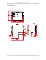
For ease of operation, the control head should be mounted in a convenient position close to your gas
appliances and in a position where the control head can be seen and heard easily. The unit can be
either surface mounted or recessed into a 2.5mm panel.
11 Sensor Installation
§
The sensor is supplied with a 5-meter cable.
§
For LPG and Petrol fumes, which are heavier than air, mount the sensor in a low dry position
where the gas is likely to collect. The sensor must be mounted clear of bilge water.
NOTE: If the sensor gets wet then the sensor becomes inoperable and must be replaced.
§
For CNG, which is lighter than air, mount the sensor just below ceiling height but not above
cooking or heating appliances.
§
Fasten the sensor with the supplied screws.
§
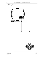
Route the sensor cable through to the control head and connect as per the wiring diagram.
12 Operation
On applying power to the unit, the control head goes through a test cycle. This will take approximately
45 seconds. During this period the sensor heads are being cleaned and tested, at this time there will
be a slow beep from the audible alarm and all the lights will flash amber. Towards the end of this
period the pulse of the beeper and lights will increase, if the unit senses that the environment is clear
then the control head will go into safe mode. The beeper will turn off and the sensor lights will change
to green.
13 Test Button
When operated in normal operation it will -
§
Sounds the keyboard beeper
§
Turn light red
Pressing the switch again cancels the above.
14 Indicator Display
SENSOR
Green:
Sensor on safe, no fumes, no beeping
Amber:
Sensor fault, slow beeping
Red:
Alarm. Gas present, fast beeping
AUDIBLE ALARM SOUNDS
Warming up:
Medium slow, all lights flash amber
Alarm:
Fast, sensor lights red
Fault:
Slow, sensor lights amber

